Introduction: Evolution of Vibration Monitoring
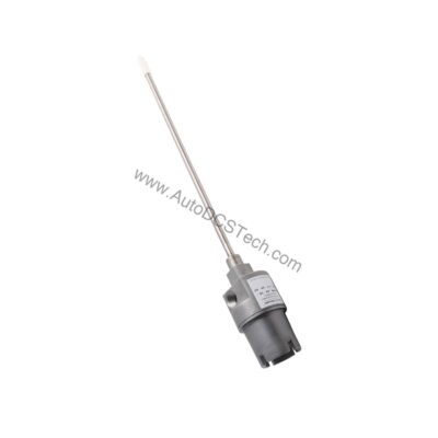
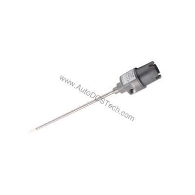
Vibration monitoring has evolved from simple mechanical switches to sophisticated electronic transmitters that provide continuous, real-time data. The 990-05-50-03-01 from Bently Nevada represents this evolution, offering a compact, loop-powered solution for industrial machinery protection.
This transmitter accepts one non-contacting 3300 NSv proximity probe and extension cable, converting dynamic vibration into a standard 4-20 mA signal. With a full-scale range of 0-5 mils pp (0-125 μm pp), it delivers precise measurements for critical rotating equipment.
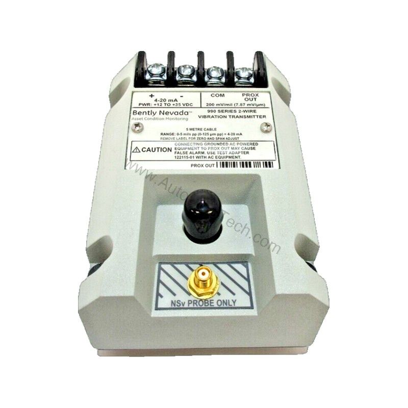
Key Features of the 990-05-50-03-01
- Accepts 1 non-contacting 3300 NSv proximity probe and extension cable.
- Requires +12 to +35 Vdc input at the transmitter terminal.
- Provides 4-20 mAdc output over the specified full-scale range in a 2-wire configuration.
- Offers 4-20 mA loop accuracy within ±1.5% over the full-scale range.
- Features non-interacting external zero and span adjustments.
- Includes NOT OK/signal defeat: output goes to less than 3.6 mA within 100 µs after a Not OK condition.
- Frequency response: 5 Hz to 6,000 Hz +0, 3 dB.
- Maximum loop resistance: 1,000 Ω including cable at 35 Vdc.
- Current limiting: 23 mA typical.
These specifications ensure reliable performance in demanding industrial environments.
Applications and Use Cases
The 990-05-50-03-01 is ideal for monitoring vibration on pumps, motors, fans, and other rotating machinery. Its 4-20 mA output integrates easily with PLCs, DCS, and SCADA systems, enabling predictive maintenance strategies.
Because it accepts a 3300 NSv probe, it is suitable for retrofit projects where existing probes are in place. The compact DIN rail mounting (35 mm) simplifies installation in control panels.
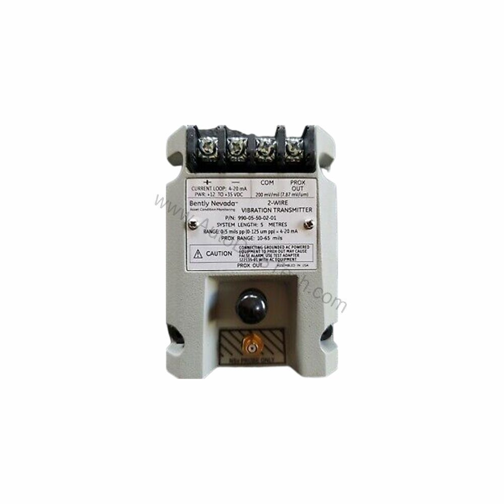
Installation and Setup
Mount the transmitter using the provided DIN clips and screws (mounting option 03). The system length option 50 specifies a 5.0-meter (16.4 feet) cable, ensuring flexibility in field wiring.
Power the transmitter with +12 to +35 Vdc at the terminal. The probe must be gapped between 0.5 and 1.75 mm (20 and 55 mils) from the target to ensure full-scale range. Ensure the maximum leadwire length for the Proximitor Sensor Output (BNC connector) does not exceed 3 meters (10 feet).
Maintenance and Reliability
Regular inspection of the probe and cable is recommended to maintain measurement accuracy. Verify that the probe gap remains within the specified range and that all connections are secure.
The transmitter's robust design and current limiting (23 mA typical) protect against overcurrent conditions. Periodic calibration checks help sustain the ±1.5% accuracy.
Compatibility and Integration
The 4-20 mA output is universally compatible with most industrial control systems. The transmitter operates in non-hazardous, Zone 2, or Div 2 hazardous area locations with a power supply of 28 V.
Its 2-wire configuration simplifies wiring, reducing installation costs. The DIN rail mounting option (35 mm) fits standard enclosures.
Troubleshooting Common Issues
If the output signal drops below 3.6 mA, a Not OK condition is indicated. This could be due to probe damage, incorrect gap, or wiring faults. The signal restores within 2-3 seconds after the condition is removed.
Check the loop resistance—maximum 1,000 Ω at 35 Vdc—to ensure the transmitter can drive the load. Verify the power supply voltage is within +12 to +35 Vdc.
Product Support and Availability
The 990-05-50-03-01 is available from AutoDCSTech. Please verify current lifecycle status and availability with AutoDCSTech before ordering.