Introduction to the 990-10-70-01-CN
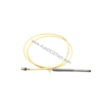
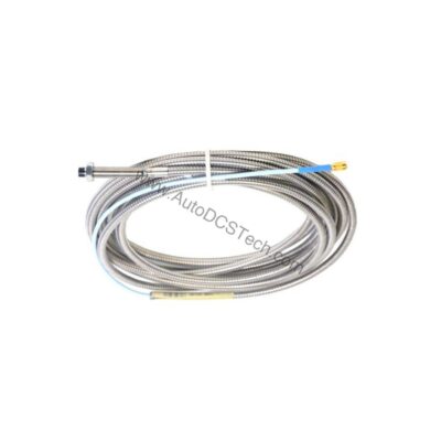
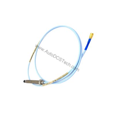
When machine vibration threatens uptime, the 990-10-70-01-CN delivers a precise, loop-powered signal for continuous monitoring. This Bently Nevada 990 Vibration Transmitter accepts one non-contacting 3300 NSv Proximity Probe and extension cable, converting shaft vibration into a standard 4-20 mA output. Its compact design and 35 mm DIN rail clips simplify installation in existing panels.
With a full-scale range of 0-10 mils pp (0-250 μm pp), the transmitter is suited for rotating machinery protection. The 7.0-meter (23.0 feet) system length offers flexibility in probe placement. This model carries country-specific approvals (CN), ensuring compliance for your region.
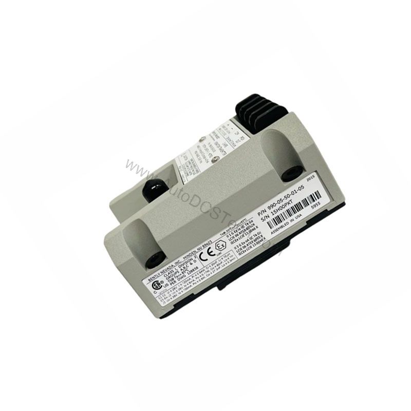
Key Features and Technical Specifications
The 990-10-70-01-CN is engineered for accuracy and reliability. Its 4-20 mA output provides a direct interface to PLCs, DCS, and standalone monitors. The loop-powered design simplifies wiring and reduces cost.
- Input: Accepts 1 non-contacting 3300 NSv Proximity Probe and extension cable.
- Power: Requires +12 to +35 Vdc input at the transmitter terminal.
- Output: 4 to 20 mAdc over specified full-scale range in 2-wire configuration.
- Accuracy: Within ±1.5% over specified full-scale range (from TEST signal input to voltage across a 250 Ω loop resistance).
- Maximum Loop Resistance: 1,000 Ω including cable at 35 Vdc.
- Current Limiting: 23 mA typical.
- Frequency Response: 5 Hz to 6,000 Hz +0, 3 dB.
- Minimum Target Size: 9.5 mm (0.375 in) diameter.
- Mounting: 35 mm DIN rail clips.
- Weight: 0.43 kg (0.9 lbm).
These specifications directly impact cost efficiency. The wide power range (+12 to +35 Vdc) reduces the need for dedicated power supplies. The high loop resistance (1,000 Ω) allows longer cable runs without extra signal conditioners. The ±1.5% accuracy minimizes false alarms, reducing maintenance and downtime costs.
Applications and Use Cases
In petrochemical plants, the 990-10-70-01-CN monitors pumps and compressors. Its 0-10 mils range covers typical vibration levels. The 4-20 mA output feeds directly into existing control systems, avoiding costly upgrades. For example, a refinery can use this transmitter on cooling tower fans, where early detection of imbalance prevents unplanned shutdowns.
In power generation, the transmitter monitors turbine shaft vibration. The frequency response of 5 Hz to 6,000 Hz captures both low-speed and high-speed events. This broad range helps avoid catastrophic failures, saving millions in repair costs.
Installation and Setup
Mount the 990-10-70-01-CN on a 35 mm DIN rail. Ensure the probe is gapped between 0.5 and 1.75 mm (20 and 55 mils) from the target. This gap is critical for full-scale range. Connect the probe and extension cable to the transmitter. Apply +12 to +35 Vdc power. The 4-20 mA loop connects to your monitoring system.
Non-interacting external zero and span adjustments simplify calibration. Use a 250 Ω resistor across the loop to verify accuracy. The maximum leadwire length for the Proximitor Sensor Output (BNC connector) is 3 meters (10 feet). Proper installation reduces commissioning time and costs.
Maintenance and Reliability
Regular inspection ensures long-term reliability. Check the probe gap periodically. Verify the loop current is within the 4-20 mA range. The transmitter's current limiting (23 mA typical) protects against overcurrent. The NOT OK/signal defeat function forces the output below 3.6 mA within 100 µs of a fault, alerting operators quickly.
This fast response reduces diagnostic time. The output restores within 2-3 seconds after the Not OK condition clears. This feature minimizes downtime and helps avoid unnecessary process trips. Routine maintenance is simple: verify connections and calibration. No special tools are required.
Compatibility and Integration
The 990-10-70-01-CN works with any system accepting 4-20 mA signals. This includes PLCs, DCS, and standalone vibration monitors. The 2-wire configuration reduces wiring costs. The transmitter is compatible with Bently Nevada 3300 NSv proximity probes and extension cables.
For hazardous area locations (NonHazardous, Zone 2 or Div 2), the power supply is 28 V. Ensure your system meets this requirement. The country-specific approval (CN) ensures compliance for your region. Integration is straightforward, reducing engineering and installation costs.
Troubleshooting and Common Issues
If the output is not within 4-20 mA, check the probe gap. Re-gap to 0.5-1.75 mm. Verify the power supply is between +12 and +35 Vdc. Check loop resistance; it must not exceed 1,000 Ω at 35 Vdc. If the output goes below 3.6 mA, a Not OK condition exists. Inspect the probe and cable for damage.
For accuracy issues, verify the calibration using the TEST signal input. Ensure the loop resistance is exactly 250 Ω during accuracy tests. If the frequency response seems off, verify the target size is at least 9.5 mm diameter. These steps help avoid false readings and reduce troubleshooting time.
Product Support and Availability
The 990-10-70-01-CN is available from AutoDCSTech. In stock and ready to ship. For technical questions, contact AutoDCSTech. Please verify current lifecycle status and availability before ordering.