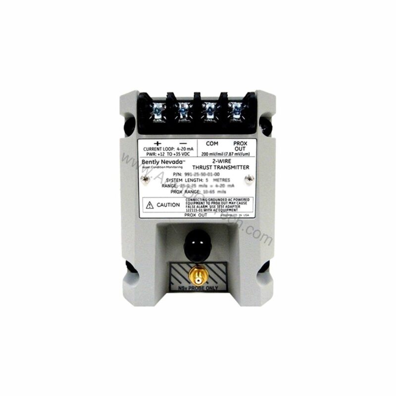
Why Precision Thrust Monitoring Matters
When axial shaft position drifts beyond safe limits, rotating machinery risks catastrophic thrust bearing failure. How do you catch that drift early? The 991-06-70-01-05 from Bently Nevada provides continuous, accurate axial position monitoring, converting probe signals into a 4-20 mA loop for reliable integration with your control system.
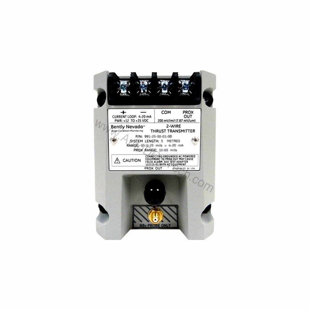
What Is the 991-06-70-01-05?
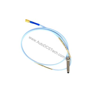
The 991-06-70-01-05 is a Probe Vibration Transmitter, specifically a Thrust Transmitter (Model 991). It accepts one non-contacting 3300 NSv proximity probe and extension cable, then outputs a 4-20 mA signal proportional to axial displacement. This two-wire transmitter is designed for DIN-rail mounting and operates from a +12 to +35 Vdc supply at the transmitter terminal.
Key Features and Technical Specifications
The 991-06-70-01-05 delivers precise, repeatable thrust measurement with these core specs:
- Full-scale range: 0.6-0-0.6 mm (suitable for 25-0-25 mils current loop linear ranges)
- Output signal: 4-20 mA dc (two-wire configuration)
- Power requirement: +12 to +35 Vdc input at the transmitter terminal
- Linear range: 0.25 to 1.65 mm for Prox Out
- Loop accuracy: Within ±1.5% over specified full scale (typical)
- Maximum loop resistance: 1,000 Ω including cable at 35 Vdc
- Current limiting: 23 mA typical
- Not OK/Signal Defeat: Output drops to <3.6 mA within 100 µs after a Not OK condition; restores within 0.1 s
- Zero and span: Non-interacting external adjustments
These parameters ensure reliable operation in demanding environments, with a transmitter operating temperature range of -35°C to +85°C and storage from -51°C to +100°C.
Installation and Mounting
Mounting the 991-06-70-01-05 is straightforward. The unit comes with 35 mm DIN-rail clips (Mounting Option 01), allowing quick, secure attachment to standard rails. The system length option of 7.0 meters (23.0 feet) provides flexibility for probe placement. For setup, connect the 3300 NSv probe and extension cable, then wire the 4-20 mA loop to your monitoring system. Ensure the supply voltage is within +12 to +35 Vdc at the transmitter terminal.
Applications and Use Cases
This transmitter is ideal for axial thrust monitoring in turbomachinery, compressors, and large pumps. In these applications, maintaining proper thrust bearing clearance is critical. The 991-06-70-01-05 provides continuous 4-20 mA output that can feed into PLCs, DCS, or dedicated vibration monitoring systems. Its fast Not OK response (<3.6 mA within 100 µs) enables rapid shutdown logic, protecting equipment from damage.
Maintenance and Reliability
Regular inspection of the probe and cable is essential. Check for physical damage, loose connections, and proper probe gap. The transmitter's robust design, with no moving parts, minimizes maintenance. Its wide temperature range ensures stable performance in harsh environments. For long-term reliability, verify loop resistance stays below 1,000 Ω and supply voltage remains within specified limits.
Compatibility and Integration
The 991-06-70-01-05 integrates easily with any system accepting 4-20 mA analog inputs. It is compatible with Bently Nevada 3300 NSv proximity probes and extension cables. The two-wire configuration simplifies wiring, reducing installation cost. The non-interacting zero and span adjustments allow quick calibration on site.
Troubleshooting Common Issues
If the output is not as expected, check the following:
- Verify supply voltage at the transmitter terminal is between +12 and +35 Vdc.
- Confirm loop resistance (including cable) does not exceed 1,000 Ω.
- Inspect probe and extension cable for damage or loose connections.
- Ensure the probe is within its linear range (0.25 to 1.65 mm).
- If output goes below 3.6 mA, a Not OK condition exists; check probe gap and wiring.
Product Support and Availability
The 991-06-70-01-05 is available through AutoDCSTech. For ordering or technical questions, contact our team. As with any industrial component, verify current lifecycle status and availability with AutoDCSTech before ordering.