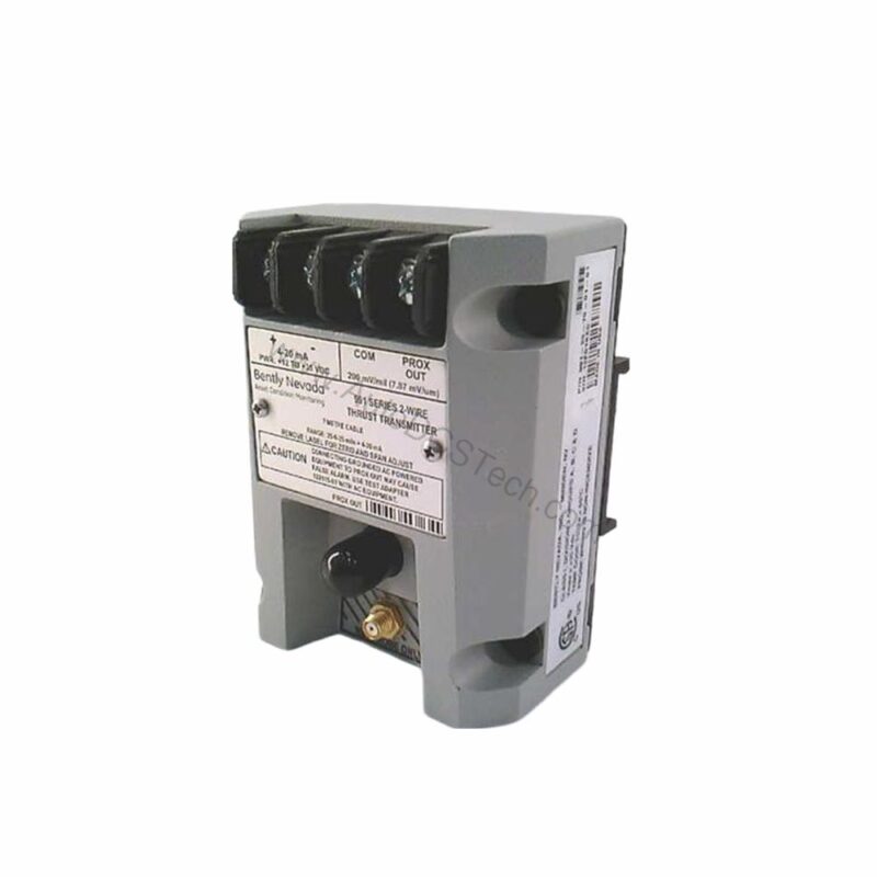
Introduction to the 991-25-70-02-05
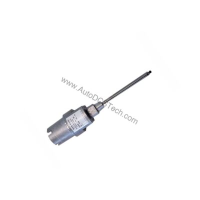
When axial thrust monitoring demands precision and reliability, the 991-25-70-02-05 from Bently Nevada stands ready. This Probe Vibration Transmitter is engineered to convert non-contacting proximity probe signals into a standard 4-20 mA output, ideal for industrial rotating machinery protection.
Part of the 991 Thrust Transmitter series, this model is configured with a full-scale range of 25-0-25 mils and a system length of 7.0 meters (23.0 feet). It is designed for DIN rail mounting and includes agency approvals for CSA Division 2, ATEX Zone 0, ATEX Zone 2, and ABS maritime applications.
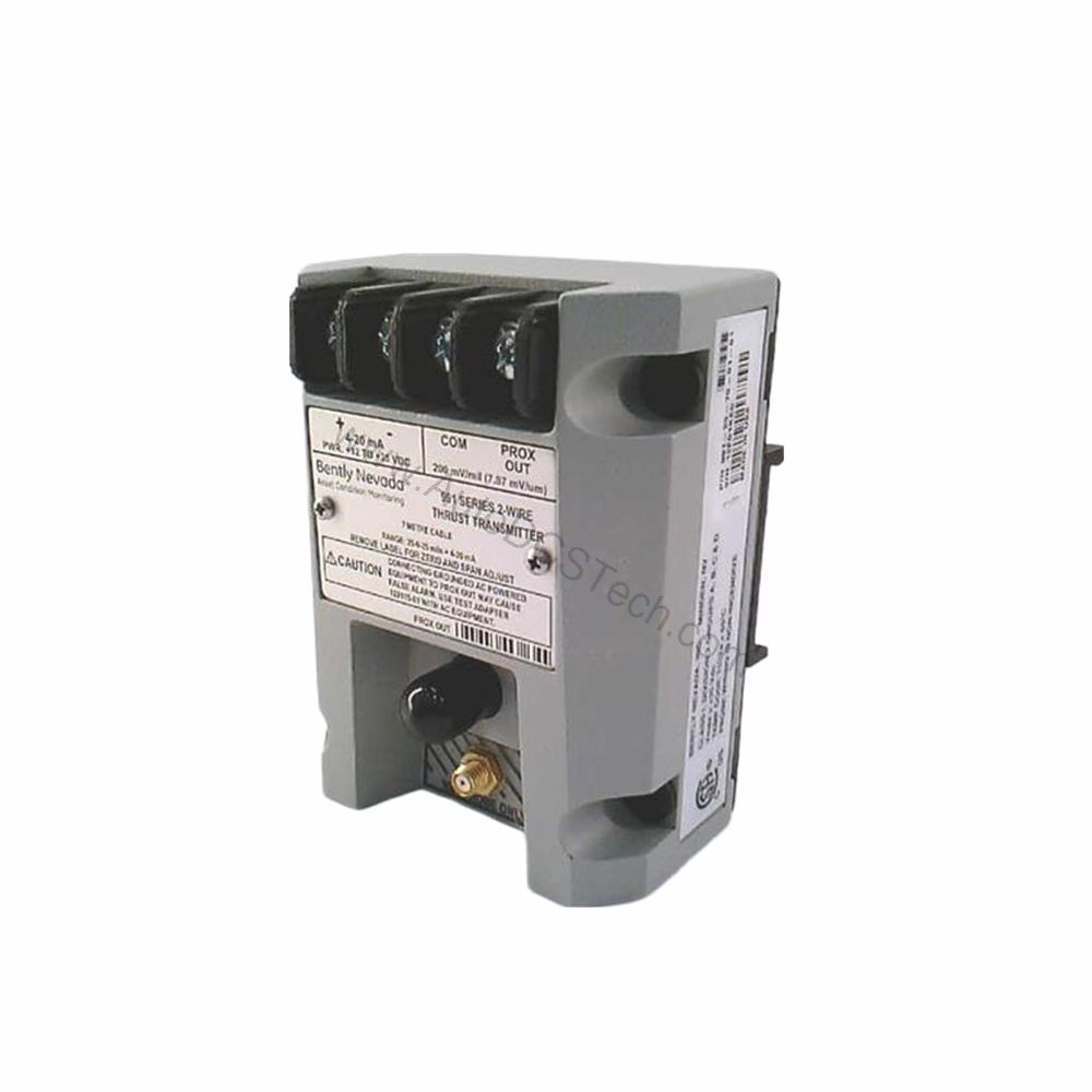
Key Features and Technical Specifications
The 991-25-70-02-05 offers a robust set of features tailored for continuous vibration and thrust monitoring. Below are the core specifications extracted directly from the manufacturer's data:
- Output Signal: 4-20 mA DC in a 2-wire configuration, proportional to the full-scale range.
- Power Requirement: +12 to +35 Vdc input at the transmitter terminal.
- Linear Range: 0.25 to 1.65 mm for Prox Out, suitable for 0.6-0-0.6 mm or 25-0-25 mils current loop linear ranges.
- Loop Accuracy: Within ±1.5% over specified full-scale range (typical), rated from TEST signal input to voltage across a 250 Ω loop resistance.
- Maximum Loop Resistance: 1,000 Ω including cable at 35 Vdc.
- Current Limiting: 23 mA typical.
- Zero and Span: Non-interacting external adjustments.
- Not OK/Signal Defeat: Output drops to less than 3.6 mA within 100 µs after a Not OK condition, restored within 0.1 seconds after removal.
These specifications ensure accurate and reliable signal transmission, critical for predictive maintenance and machine protection systems.
Applications and Use Cases
The 991-25-70-02-05 is specifically designed for axial thrust monitoring in turbomachinery, compressors, and large rotating equipment. Its 4-20 mA output integrates seamlessly with PLCs, DCS, and SCADA systems, enabling real-time data acquisition and alarm management.
With its ATEX and CSA approvals, this transmitter is suitable for hazardous area installations, including Zone 0 and Zone 2 environments. The ABS maritime approval extends its use to marine propulsion systems and offshore platforms, where reliability and safety are paramount.
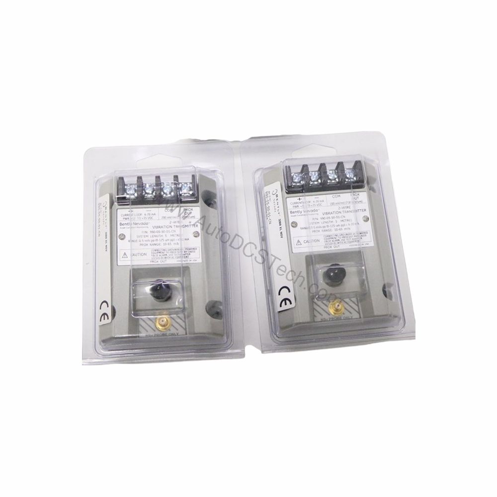
Installation and Mounting
Mounting the 991-25-70-02-05 is straightforward with the included bulkhead screws (Mounting Option 02). The transmitter is designed for DIN rail installation, simplifying panel integration and reducing installation time.
For optimal performance, ensure the proximity probe and extension cable are correctly connected to the transmitter. The system length of 7.0 meters (23.0 feet) provides flexibility in probe placement while maintaining signal integrity.
Maintenance and Reliability
Regular inspection of the transmitter and its connections is essential to ensure long-term reliability. The unit's non-interacting zero and span adjustments allow for quick calibration without disturbing the loop.
The Not OK/Signal Defeat feature enhances system safety by rapidly indicating fault conditions, minimizing downtime and preventing potential damage to rotating machinery. Periodic verification of the output signal against a known reference is recommended per manufacturer guidelines.
Compatibility and Integration
The 991-25-70-02-05 accepts one non-contacting 3300 NSv proximity probe and extension cable, making it compatible with Bently Nevada's 3300 series sensors. The 4-20 mA output is universally accepted by most control systems, ensuring easy integration into existing monitoring architectures.
For applications requiring higher loop resistance, the transmitter supports up to 1,000 Ω at 35 Vdc, accommodating long cable runs without signal degradation.
Troubleshooting Common Issues
If the output signal is not within the expected range, verify the power supply voltage is between +12 and +35 Vdc. Check the loop resistance and ensure it does not exceed 1,000 Ω. Confirm that the probe and extension cable are properly connected and free from damage.
If the Not OK condition persists, inspect the probe gap and target surface for anomalies. Refer to the Bently Nevada manual for detailed troubleshooting procedures.
Product Support and Availability
The 991-25-70-02-05 is available through AutoDCSTech, an industrial automation parts supplier. Please verify current lifecycle status and availability with AutoDCSTech before ordering.