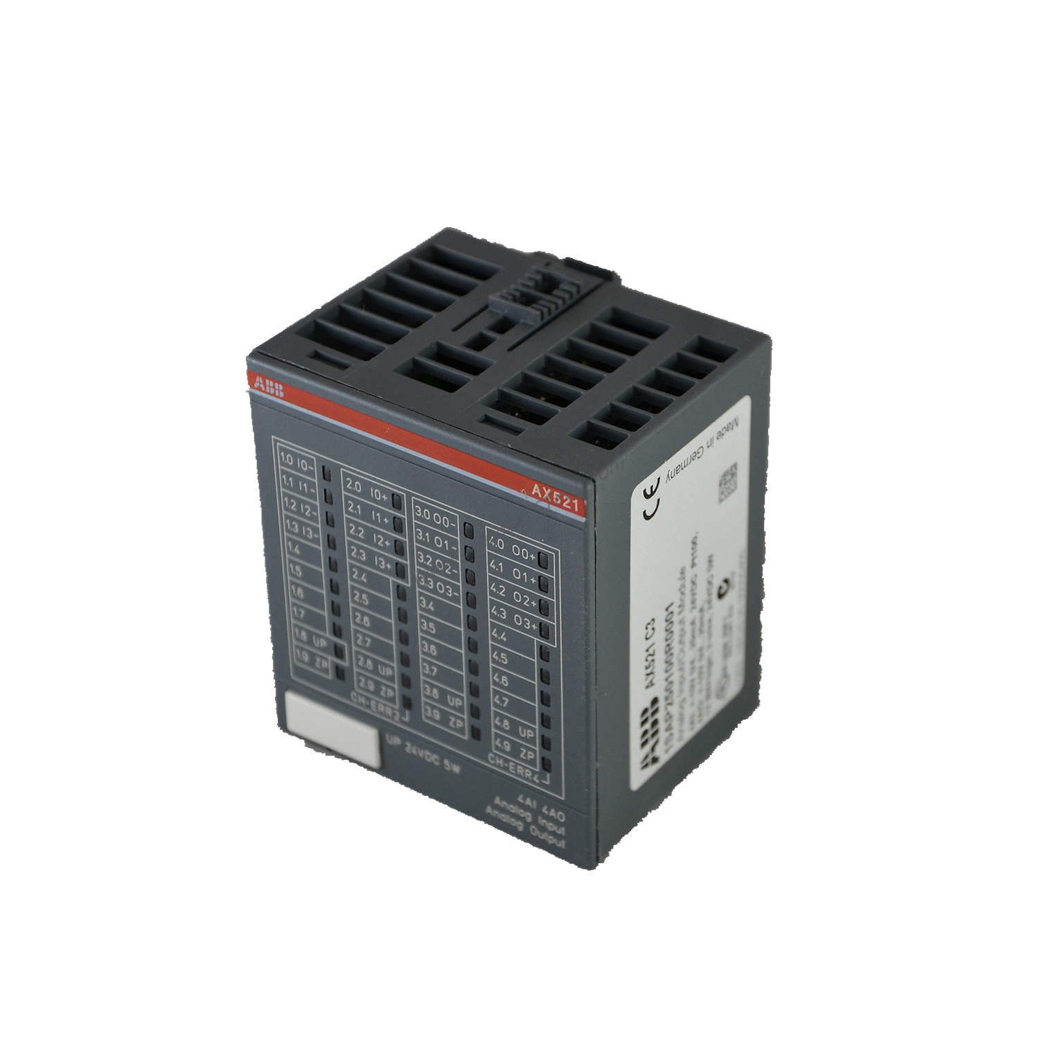
Introduction
Designed for bipolar (not with current or Pt100/Pt1000/Ni1000) voltage signals, this module combines 8 analog inputs and 8 analog outputs in a single compact unit. With 12-bit plus sign resolution and galvanic isolation per module, the AX522 ensures reliable data acquisition in electrically noisy environments.
Technical Specifications Breakdown
The AX522 offers configurable input ranges including 0 V...10 V, -10 V...+10 V, 0 mA...20 mA, and 4 mA...20 mA, with each input individually configurable. The input resistance for voltage is greater than 100 kW, while current inputs have approximately 330 W resistance. The conversion cycle is 2 ms for 8 inputs plus 8 outputs, extending to 1 s when using Pt/Ni sensors. Resolution reaches 12 bits for unipolar ranges and 12 bits plus sign for the -10 V...+10 V range. Typical conversion error is ±0.5% of full scale at 25 °C, with a maximum of ±1% over the 0 °C to 60 °C temperature range or under EMC disturbance.
Industry Applications
In a typical manufacturing line, the AX522 monitors voltage signals from pressure transducers and temperature sensors while simultaneously driving analog actuators. For example, in a plastic extrusion process, the module reads melt pressure (0-10 V) and barrel temperature (-10 V to +10 V) from eight sensors, then outputs control signals to eight proportional valves. The 2 ms conversion cycle ensures real-time response, while the per-module galvanic isolation prevents ground loops between sensors and the controller.
Installation & Setup Guidance
Mount the AX522 horizontally or vertically, noting that vertical mounting requires derating output loads to 50% at 40 °C per group. Ensure natural convection cooling remains unobstructed by cable ducts or other components. Connect +24 V (UP) to terminals 1.8, 2.8, 3.8, and 4.8, and 0 V (ZP) to terminals 1.9, 2.9, 3.9, and 4.9. Use a 10 A fast fuse on the UP supply for protection. For analog cables, maintain a conductor cross-section greater than 0.14 mm² and keep cable length under 100 m. Unused voltage inputs should be configured as "unused" in software, while unused current inputs can remain open-circuited.
Maintenance & Reliability
The AX522 includes overvoltage protection and reverse voltage protection, reducing the risk of damage from wiring errors. Its typical conversion error of ±0.5% at 25 °C ensures consistent accuracy over time. For long-term reliability, periodically inspect the module for dust accumulation that could hinder natural convection cooling. The module draws approximately 2 mA from the 24 VDC supply and 0.15 A plus output loads from UP during normal operation, making it energy-efficient for continuous use.
Compatibility & Integration
It communicates via the module bus, requiring no additional configuration for basic analog I/O operations. The module's 8-channel group configuration simplifies wiring and reduces terminal usage. For systems requiring mixed signal types, the individually configurable inputs allow voltage, current, or RTD signals on a per-channel basis.
Selection Guide & Purchasing Advice
Before purchasing the AX522, verify that your application requires bipolar (not with current or Pt100/Pt1000/Ni1000) inputs and that the 8 AI / 8 AO channel count meets your needs. Confirm the 24 VDC power supply is available and that the mounting orientation allows adequate airflow. Please verify current lifecycle status and availability with AutoDCSTech before ordering. AutoDCSTech stocks the AX522 (part number 1SAP 250 000 R0001) and can provide technical support for integration.
Troubleshooting & Common Issues
If the module fails to communicate, check the 24 VDC supply at terminals UP and ZP, ensuring the 10 A fuse is intact. For inaccurate readings, verify that input ranges are configured correctly for each channel and that analog cables do not exceed 100 m. If outputs are not responding, confirm that output loads do not exceed the derated capacity when mounted vertically. Overvoltage protection prevents damage from transient spikes, but persistent overvoltage may indicate a wiring fault.
Frequently Asked Questions
Q1: Can the AX522 handle current inputs like 4-20 mA?
Yes, the AX522 supports 0 mA...20 mA and 4 mA...20 mA ranges, configurable per input channel. However, the module is classified as bipolar (not with current or Pt100/Pt1000/Ni1000) for its primary input type.
Q2: What is the maximum cable length for analog signals?
The maximum analog cable length is 100 m, provided the conductor cross-section is greater than 0.14 mm².
Q3: Does the AX522 provide galvanic isolation?
Yes, galvanic isolation is provided per module, separating the module from the internal supply and other modules.
Q4: How do I configure unused input channels?
Unused voltage inputs should be configured as "unused" in the software. Unused current inputs have low resistance and can be left open-circuited.
Q5: What is the conversion cycle time for all channels?
The conversion cycle is 2 ms for 8 inputs plus 8 outputs. When using Pt/Ni sensors, the cycle extends to 1 s.
Availability & Condition at AutoDCSTech
| Part Number | AX522 |
|---|---|
| Availability | In Stock |
| Condition | New |
| Warranty | One Year |
| Origin | Switzerland |