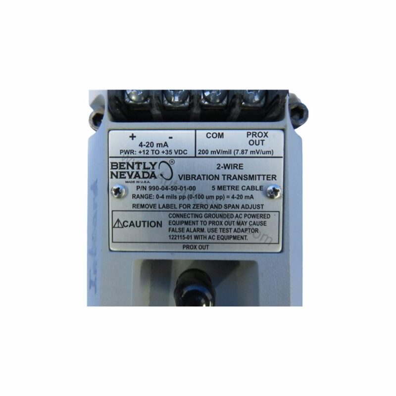
Introduction to the 990-04-50-01-05 Vibration Transmitter
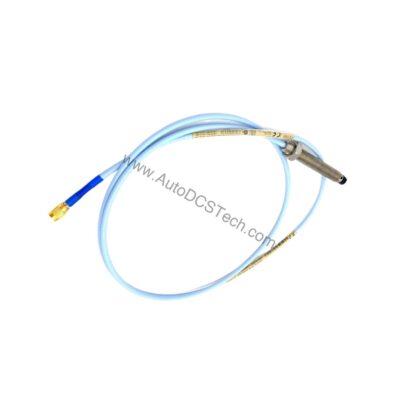
When machine vibration threatens uptime, the 990-04-50-01-05 from Bently Nevada delivers a reliable 4-20 mA signal proportional to shaft vibration. This 990 series transmitter accepts one non-contacting 3300 NSv proximity probe and extension cable, converting dynamic motion into a standard industrial signal for monitoring systems.
With a full-scale range of 0-4 mils peak-to-peak (0-100 μm pp), the 990-04-50-01-05 suits rotating machinery such as pumps, motors, and fans where early warning prevents costly failures. Its compact DIN-rail mount simplifies installation in existing panels.
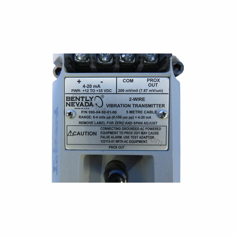
Key Features and Technical Specifications
The 990-04-50-01-05 operates on a +12 to +35 Vdc supply at the transmitter terminal, making it flexible for various control cabinets. Its 4-20 mA output is accurate to within ±1.5% over the full-scale range, measured across a 250 Ω loop resistance.
- Input: Accepts one 3300 NSv proximity probe and extension cable.
- Power: +12 to +35 Vdc input at the transmitter terminal.
- Output: 4-20 mA dc over the specified full-scale range in a 2-wire configuration.
- Loop Accuracy: Within ±1.5% over the full-scale range (from TEST signal to voltage across 250 Ω).
- Maximum Loop Resistance: 1,000 Ω including cable at 35 Vdc.
- Current Limiting: 23 mA typical.
- Frequency Response: 5 Hz to 6,000 Hz +0, 3 dB.
- Minimum Target Size: 9.5 mm (0.375 in) diameter.
- Probe Gap: Must be gapped between 0.5 and 1.75 mm (20 and 55 mils) for full-scale range.
- Mounting: 35 mm DIN rail clips.
- Weight: 0.43 kg (0.9 lbm).
Performance and Reliability
In vibration monitoring, signal integrity is paramount. The 990-04-50-01-05 ensures a fast response: if a Not OK condition occurs, the output drops to less than 3.6 mA within 100 µs, and it restores within 2-3 seconds after the condition clears. This rapid fault indication helps operators take immediate action.
Non-interacting external zero and span adjustments simplify calibration, reducing setup time and potential errors. The transmitter is designed for reliable operation in industrial environments, with agency approvals including CSA Division 2, ATEX Zone 0, ATEX Zone 2, and ABS maritime approval.
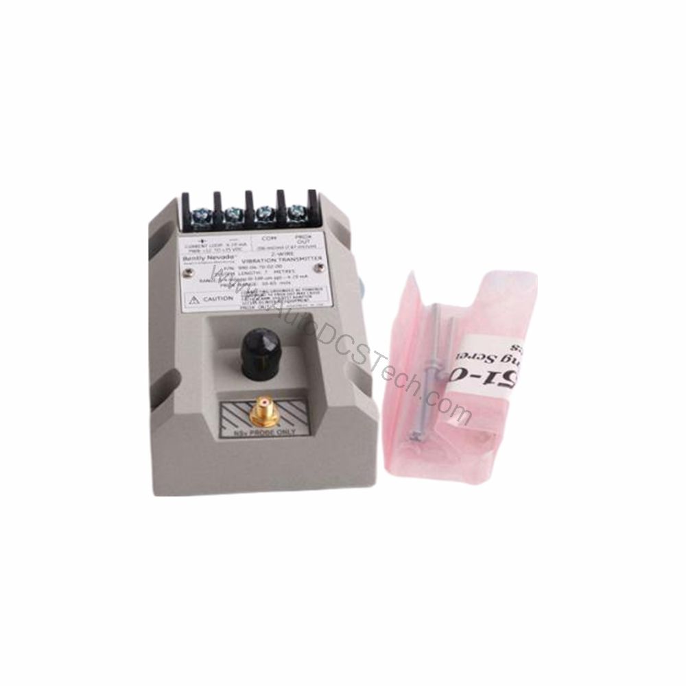
Comparison with Similar Vibration Transmitters
Compared to other loop-powered vibration transmitters, the 990-04-50-01-05 offers a specific full-scale range of 0-100 μm pp and a frequency response of 5 Hz to 6,000 Hz. Many competing units have narrower bandwidths or require separate signal conditioners. The built-in current limiting at 23 mA typical protects the loop, while the maximum loop resistance of 1,000 Ω at 35 Vdc ensures compatibility with most PLC/DCS analog inputs.
In terms of mounting, the 35 mm DIN rail clip option simplifies panel installation, whereas some transmitters require direct machine mounting. The 5.0-meter system length option provides flexibility for probe placement.
Installation and Setup
Mount the 990-04-50-01-05 on a standard 35 mm DIN rail. Connect the 3300 NSv probe and extension cable to the transmitter input. Ensure the probe gap is set between 0.5 and 1.75 mm from the target to achieve the full-scale range. Wire the 4-20 mA loop to the power supply (+12 to +35 Vdc) and the monitoring device, observing polarity.
For hazardous area installations, verify that the power supply is rated appropriately (28 V is typical for the listed approvals). Use the external zero and span adjustments for calibration, following the manual's procedure.
Maintenance and Troubleshooting
Periodically inspect the probe and cable for damage, and verify the probe gap remains within specification. Check loop resistance to ensure it does not exceed 1,000 Ω. If the output is stuck below 3.6 mA, a Not OK condition may be present—check the probe and wiring. If the output is inaccurate, verify the zero and span settings.
For detailed diagnostics, refer to the Bently Nevada manual or contact AutoDCSTech for support.
Availability and Support
The 990-04-50-01-05 is available from AutoDCSTech. Please verify current lifecycle status and availability before ordering. Our team can assist with technical questions and cross-references.