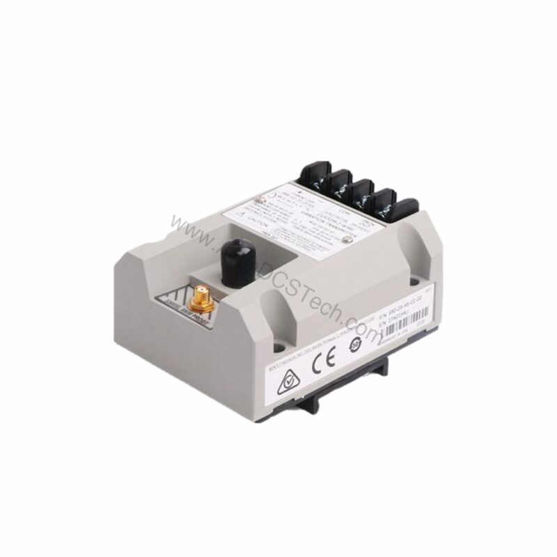
990-05-70-03-CN Vibration Transmitter Overview
When rotating machinery experiences excessive vibration, unplanned downtime and equipment damage often follow. The 990-05-70-03-CN from Bently Nevada provides a dependable solution by converting proximity probe signals into a standard 4-20 mA output. This 990 Vibration Transmitter is designed for continuous monitoring in industrial environments, helping you detect issues before they escalate.
Manufactured in the U.S.A., this unit accepts one non-contacting 3300 NSv Proximity Probe and extension cable. Its full-scale range is 0-5 mils pp (0-125 μm pp), making it suitable for applications requiring precise vibration measurement. The transmitter operates on +12 to +35 Vdc input at the terminal, with a maximum loop resistance of 1,000 Ω including cable at 35 Vdc.
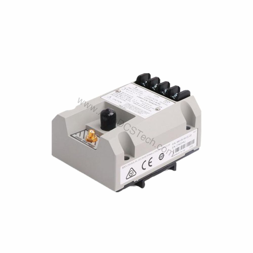
Key Features and Performance Metrics
The 990-05-70-03-CN delivers several technical advantages that address common pain points in vibration monitoring:
- Full-scale range: 0-5 mils pp (0-125 μm pp) for accurate measurement of small displacements.
- Input compatibility: Accepts 1 non-contacting 3300 NSv Proximity Probe and extension cable.
- Power requirement: +12 to +35 Vdc input at the transmitter terminal, offering flexibility in supply voltages.
- 4-20 mA output: Provides a standard industrial signal over the specified full-scale range in a 2-wire configuration.
- Loop accuracy: Within ±1.5% over the full-scale range, measured from TEST signal input to voltage across a 250 Ω loop resistance.
- Current limiting: 23 mA typical, protecting the loop from overcurrent conditions.
- NOT OK/signal defeat: Output drops to less than 3.6 mA within 100 µs after a Not OK condition, and restores within 2-3 seconds after removal.
- Frequency response: 5 Hz to 6,000 Hz +0, 3 dB, covering typical machine vibration frequencies.
- Minimum target size: 9.5 mm (0.375 in) diameter.
These specifications ensure reliable performance in demanding applications. The non-interacting external zero and span adjustments simplify calibration, reducing setup time.
Installation and Setup Guidance
Proper installation is critical for accurate vibration measurement. The 990-05-70-03-CN includes a system length option of 7.0 meters (23.0 feet) and a mounting option of DIN clips and screws, facilitating secure attachment in control panels or junction boxes.
When installing, ensure the probe is gapped between 0.5 and 1.75 mm (20 and 55 mils) from the target to achieve full-scale range. The maximum leadwire length for the Proximitor Sensor Output (BNC connector) is 3 meters (10 feet). Verify that the power supply provides +12 to +35 Vdc at the transmitter terminal, and that total loop resistance does not exceed 1,000 Ω at 35 Vdc.
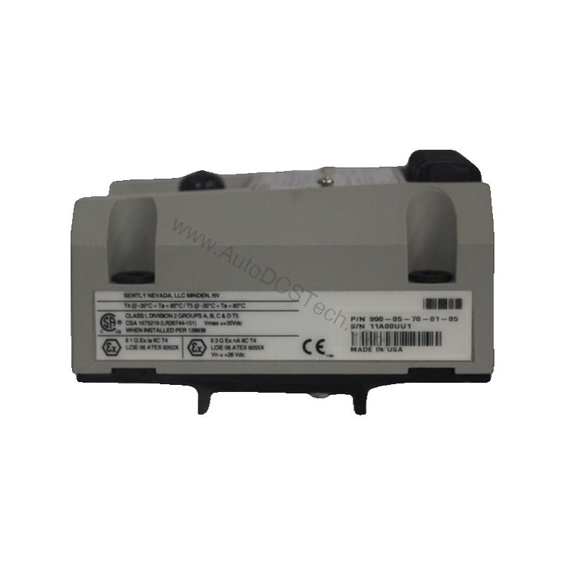
For hazardous area locations (Non-Hazardous, Zone 2 or Div 2), a 28 V power supply is specified. Always follow the manufacturer's installation manual and local electrical codes.
Maintenance and Reliability
Regular inspection of the 990-05-70-03-CN ensures long-term reliability. Periodically verify that the probe gap remains within the specified range, as target movement can affect readings. Check all connections for tightness and corrosion, especially in harsh environments.
The transmitter's current limiting feature (23 mA typical) protects the loop from faults, reducing the risk of damage to downstream equipment. The NOT OK signal defeat function provides fast fault indication, enabling prompt corrective action. For safety-rated applications, follow the manufacturer's safety manual for inspection intervals and procedures.
Applications and Use Cases
The 990-05-70-03-CN is ideal for monitoring vibration on rotating machinery such as pumps, motors, fans, and compressors. Its 4-20 mA output integrates easily with PLCs, DCS, and SCADA systems, enabling centralized condition monitoring.
In a typical scenario, a plant engineer installs this transmitter on a critical pump. The 4-20 mA signal feeds into a control system, where vibration trends are tracked. When vibration exceeds a threshold, the system alerts operators, allowing maintenance to be scheduled before failure occurs. This proactive approach reduces unplanned downtime and extends equipment life.
Troubleshooting Common Issues
If the output signal is not within expected range, first check the probe gap. An incorrect gap (outside 0.5-1.75 mm) can cause full-scale errors. Next, verify the supply voltage at the transmitter terminal is within +12 to +35 Vdc. Also, measure loop resistance to ensure it does not exceed 1,000 Ω at 35 Vdc.
If the output goes below 3.6 mA, a Not OK condition may be present. Check the probe and cable for damage, and confirm the target is within the minimum size of 9.5 mm diameter. For persistent issues, consult the Bently Nevada documentation or contact AutoDCSTech for technical support.
Product Support and Availability
The 990-05-70-03-CN is available through AutoDCSTech. Please verify current lifecycle status and availability with AutoDCSTech before ordering. Our team can assist with technical questions and provide documentation.