Introduction to the 991-06-50-01-00
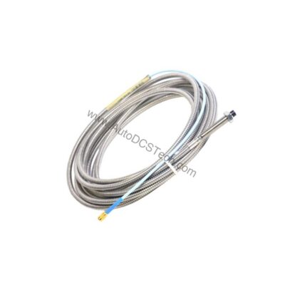
When axial thrust monitoring demands precision, the 991-06-50-01-00 from Bently Nevada provides a reliable solution. This probe vibration transmitter converts proximity probe signals into a standard 4-20 mA output, enabling seamless integration with control systems. Designed for continuous operation, it helps protect critical rotating machinery from thrust-related damage, reducing unplanned downtime and maintenance costs.
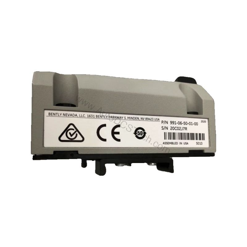
Key Features and Technical Specifications
- Full-scale option: 0.6-0-0.6 mm (25-0-25 mils) current loop linear range.
- System length: 5.0 meters (16.4 feet) integral cable.
- Mounting: 35 mm DIN-rail clips for secure installation.
- Output signal: 4-20 mA in a 2-wire configuration.
- Power requirement: +12 to +35 Vdc input at the transmitter terminal.
- Linear range: 0.25 to 1.65 mm for Prox Out.
- Accuracy: within ±1.5% over specified full scale (typical).
- Operating temperature: -35°C to +85°C (-31°F to +185°F).
- Weight: 0.43 kg (0.9 lbm).
These specifications ensure accurate and stable performance, directly contributing to lower operational costs by minimizing false trips and extending machinery life.
Applications and Use Cases
The 991-06-50-01-00 is ideal for axial position monitoring in turbines, compressors, and large pumps. In these applications, precise thrust measurement is critical to prevent rotor-to-stator contact. By providing a continuous 4-20 mA signal, the transmitter enables predictive maintenance strategies that reduce costly repairs. Furthermore, its DIN-rail mounting simplifies installation in existing panels, saving labor time and expense.

Installation and Setup
Mount the transmitter on a standard 35 mm DIN rail using the included clips. Connect the non-contacting 3300 NSv proximity probe and extension cable to the input. Wire the 4-20 mA loop to your control system, ensuring the loop resistance does not exceed 1,000 Ω at 35 Vdc. Power the transmitter with +12 to +35 Vdc at the terminal. After installation, verify zero and span using the non-interacting external adjustments to match your application's full-scale range.
Maintenance and Reliability
Regularly inspect the transmitter and probe cable for physical damage or wear. Verify the output signal responds correctly to shaft movement. Because the 991-06-50-01-00 operates over a wide temperature range, it suits harsh environments, reducing the need for frequent replacements. Its robust design and low power consumption contribute to long-term reliability and lower total cost of ownership.
Cost-Benefit Analysis
Investing in the 991-06-50-01-00 delivers measurable savings. Its ±1.5% accuracy minimizes measurement errors that could lead to unnecessary shutdowns. The 4-20 mA output integrates directly with existing PLCs and DCSs, eliminating the need for additional signal conditioning equipment. Moreover, the Not OK/Signal Defeat feature (<3.6 mA within 100 µs) provides fast fault indication, enabling rapid response and reducing downtime costs.
Compatibility and Integration
The transmitter accepts one non-contacting 3300 NSv proximity probe and extension cable, ensuring compatibility with Bently Nevada's established sensor family. The 4-20 mA output is universally accepted by most control systems, simplifying integration. This plug-and-play capability reduces engineering time and installation costs.
Troubleshooting Common Issues
If the output signal is incorrect, first verify the power supply is within +12 to +35 Vdc. Check the loop resistance; exceeding 1,000 Ω can cause errors. Confirm the probe gap is within the linear range (0.25 to 1.65 mm). If the output goes below 3.6 mA, a Not OK condition exists—inspect the probe and cable for damage. These steps help avoid costly misdiagnosis and ensure reliable operation.
Product Support and Availability
The 991-06-50-01-00 is available from AutoDCSTech. Contact our team for current lead times and technical support. We help you select the right solution for your machinery protection needs.