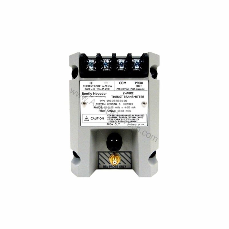
Case Study: Solving Axial Thrust Monitoring Challenges
In rotating machinery, axial shaft position is a critical parameter. Uncontrolled thrust can lead to catastrophic bearing failure and unplanned downtime. The 991-06-70-03-00 from Bently Nevada addresses this challenge directly. It converts proximity probe signals into a standard 4-20 mA loop, enabling continuous, reliable thrust monitoring.
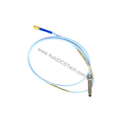
This probe vibration transmitter is engineered for axial position measurement. It accepts input from one non-contacting 3300 NSv proximity probe and extension cable. The transmitter then outputs a 4-20 mA signal proportional to shaft position, making it ideal for integration with PLCs, DCS, and SCADA systems.
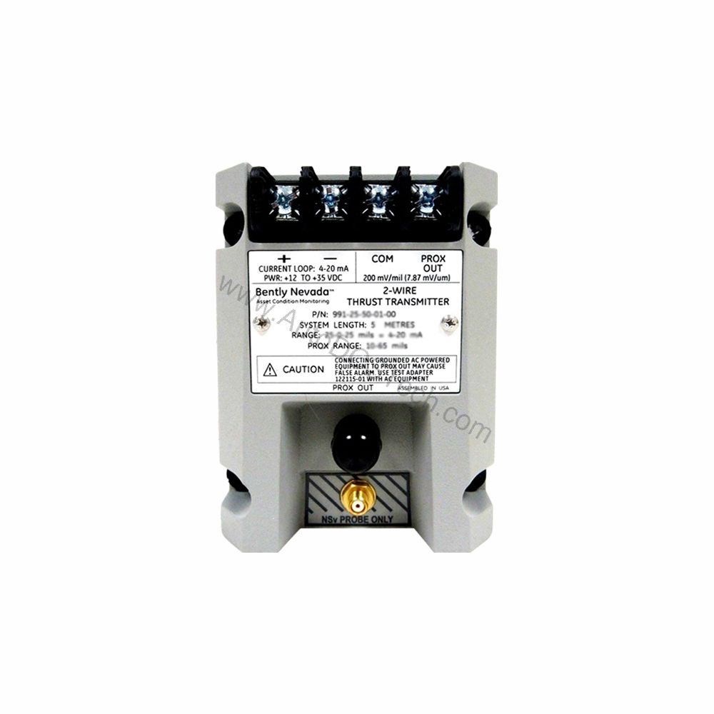
Key Features and Technical Specifications
The 991-06-70-03-00 offers a robust set of specifications designed for industrial environments. Its performance is defined by precise electrical and mechanical parameters.
- Full-Scale Option: -06 0.6-0-0.6 mm (suitable for 25-0-25 mils current loop linear ranges)
- System Length Option: -70 7.0 meters (23.0 feet) – ensures flexible installation.
- Mounting Option: 03 DIN clips and screws – simplifies panel mounting.
- Output Signal: 4-20 mA DC in a 2-wire configuration.
- Power Requirement: +12 to +35 Vdc input at the transmitter terminal.
- Linear Range: 0.25 to 1.65 mm for Prox Out.
- Operating Temperature: -35°C to +85°C (-31°F to +185°F).
- Storage Temperature: -51°C to +100°C (-60°F to +212°F).
- Weight: 0.43 kg (0.9 lbm).
One distinctive feature is the Not OK/Signal Defeat function. If a fault condition occurs, the output drops to less than 3.6 mA within 100 µs. This fast response ensures that downstream systems immediately recognize a problem, preventing erroneous readings. The signal restores within 0.1 seconds after the condition clears.
Installation and Setup
Mounting the 991-06-70-03-00 is straightforward with the DIN rail clip option. The transmitter accepts a 3300 NSv proximity probe, which must be installed per Bently Nevada guidelines. The 2-wire loop connection simplifies wiring, reducing installation time and potential errors.
For optimal performance, ensure the probe gap is set within the specified linear range. The transmitter provides non-interacting external zero and span adjustments, allowing fine calibration without affecting each other. Always verify the loop resistance does not exceed 1,000 Ω at 35 Vdc to maintain accuracy.
Applications and Use Cases
The 991-06-70-03-00 is primarily used in turbomachinery, compressors, and large pumps where axial thrust monitoring is essential. Its 4-20 mA output integrates seamlessly with existing control systems, enabling predictive maintenance strategies. For example, in a steam turbine, this transmitter can continuously feed thrust position data to a DCS, alerting operators to abnormal wear before failure occurs.
Its wide operating temperature range makes it suitable for harsh environments, from cold outdoor installations to hot machinery enclosures. The DIN rail mounting option facilitates quick replacement in retrofit projects.
Maintenance and Reliability
Routine inspection of the probe and cable is recommended to ensure reliable operation. Check for physical damage, loose connections, and proper probe gap. The transmitter itself is solid-state and requires minimal maintenance. Periodic verification of the 4-20 mA loop accuracy against a known standard is advisable.
Given its robust design, the 991-06-70-03-00 offers long service life. The current limiting feature (23 mA typical) protects the loop from overcurrent conditions. Regular calibration checks help maintain the ±1.5% accuracy specification.
Compatibility and Integration
This transmitter is designed to work with Bently Nevada 3300 NSv proximity probes and extension cables. The 4-20 mA output is universally compatible with most industrial input modules. It can be connected to PLC analog input cards, DCS AI channels, or standalone loop-powered indicators.
For new installations, verify that the system length option (7.0 meters) matches your probe-to-transmitter distance. The DIN clip mounting ensures secure attachment to standard rails.
Troubleshooting Common Issues
If the output signal is not within the expected range, first check the power supply voltage (+12 to +35 Vdc). Next, verify the probe gap and cable integrity. A Not OK condition will force the output below 3.6 mA; this is a diagnostic feature, not a malfunction.
If the loop resistance exceeds 1,000 Ω, the transmitter may not drive the signal correctly. Use a loop calibrator to measure the actual current. Also, ensure that the zero and span adjustments are set correctly for the full-scale range.
Product Support and Availability
The 991-06-70-03-00 is available from AutoDCSTech. Please verify current lifecycle status and availability with AutoDCSTech before ordering. Our team can assist with technical questions and ensure you receive the correct part for your application.