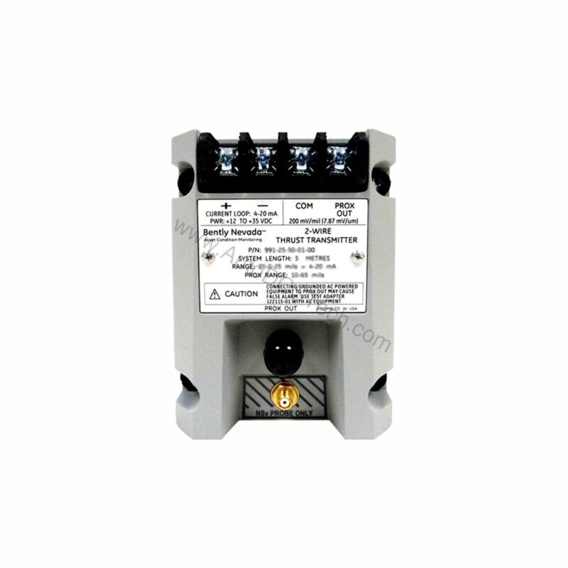
Introduction to the 991-06-70-02-00
When axial thrust exceeds safe limits, the 991-06-70-02-00 from Bently Nevada provides early warning. This probe vibration transmitter is designed for continuous monitoring of rotating machinery. It converts proximity probe signals into a standard 4-20 mA output. This enables seamless integration with PLCs, DCS, and SCADA systems.
The 991-06-70-02-00 is part of the Bently Nevada 991 series. It is built for axial thrust measurement applications. With a full-scale range of 0.6-0-0.6 mm, it delivers precise data. The transmitter operates on a +12 to +35 Vdc input. This flexibility supports various industrial power supplies.
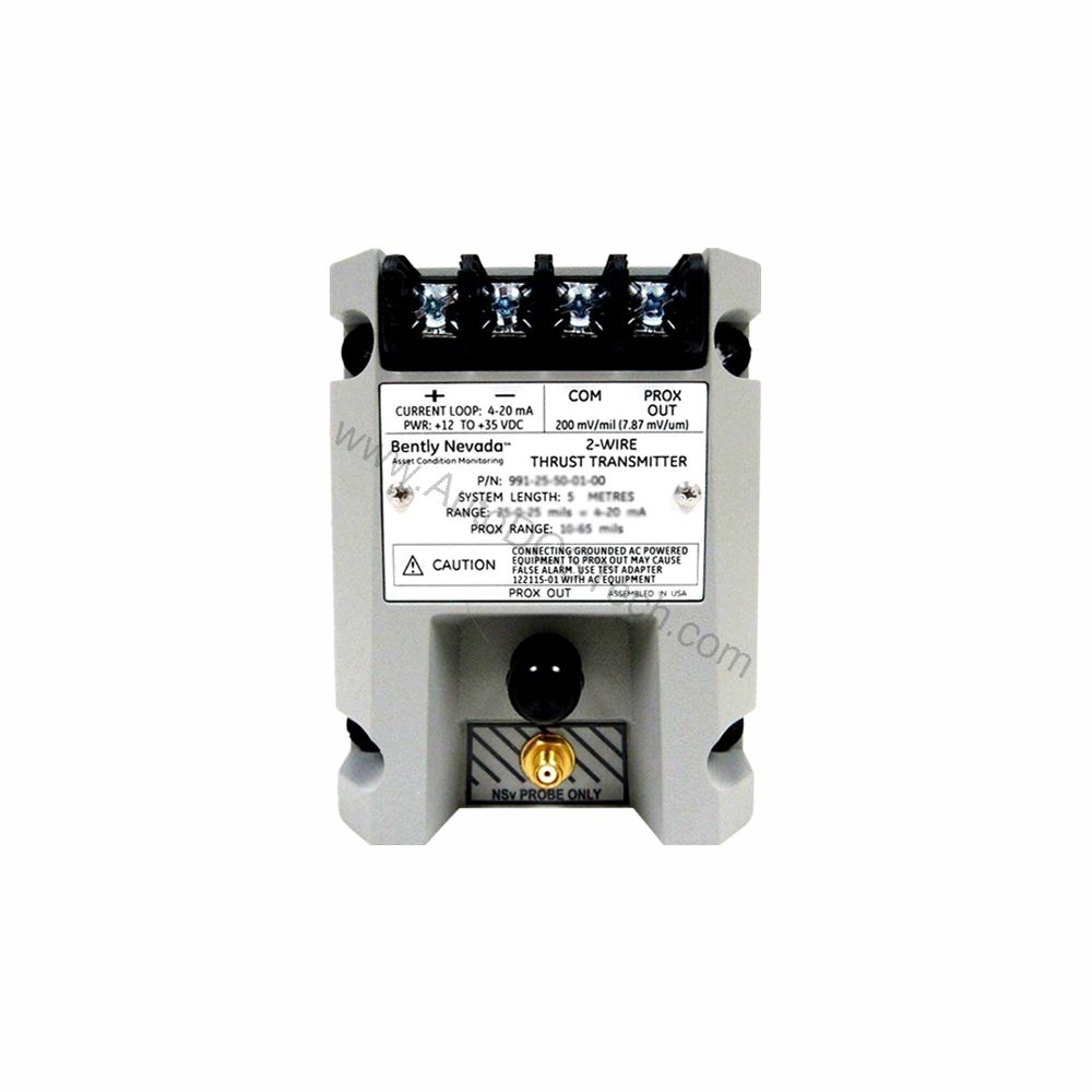
Key Features and Technical Specifications
The 991-06-70-02-00 offers several features that enhance reliability and ease of use. Below are the essential specifications derived directly from the product data.
- Output Signal: 4-20 mA DC in a 2-wire configuration.
- Power Requirement: +12 to +35 Vdc at the transmitter terminal.
- Linear Range: 0.25 to 1.65 mm for Prox Out.
- Current Limiting: 23 mA typical.
- Zero and Span: Non-interacting external adjustments.
- Not OK/Signal Defeat: Output goes below 3.6 mA within 100 µs of a fault.
The transmitter accepts one non-contacting 3300 NSv proximity probe and extension cable. This input is specifically designed for axial thrust monitoring. The 4-20 mA loop accuracy is within ±1.5% over the full-scale range. This accuracy is measured from the test signal input to the voltage across a 250 Ω loop resistance.
Performance and Reliability
The 991-06-70-02-00 is engineered for harsh industrial environments. It operates over a wide temperature range: -35°C to +85°C. Storage temperature extends from -51°C to +100°C. This ensures reliable performance in extreme conditions.
The transmitter's maximum loop resistance is 1,000 Ω including cable at 35 Vdc. This allows long cable runs without signal degradation. The Not OK/Signal Defeat feature is critical for safety. If a fault occurs, the output drops below 3.6 mA within 100 µs. This rapid response alerts control systems immediately.
Installation and Mounting
Mounting the 991-06-70-02-00 is straightforward. The unit mounts on a DIN rail. The mounting option is bulkhead screws (option 02). The system length is 7.0 meters (23.0 feet), which provides flexibility in placement.
When installing, ensure the power supply meets the +12 to +35 Vdc requirement. Connect the proximity probe to the transmitter input. Then, wire the 4-20 mA output to your monitoring system. The non-interacting zero and span adjustments simplify calibration.
Applications and Use Cases
The 991-06-70-02-00 is ideal for axial thrust monitoring in turbines, compressors, and pumps. Its 4-20 mA output integrates easily with existing control systems. This makes it suitable for both new installations and retrofits.
In a typical scenario, the transmitter continuously measures shaft axial position. If the shaft moves beyond the safe range, the output signal changes. This triggers alarms or shutdowns, preventing catastrophic damage. The transmitter's fast response to Not OK conditions enhances machinery protection.
Maintenance and Troubleshooting
Regular inspection of the 991-06-70-02-00 is recommended. Verify that the probe and cable are securely connected. Check the power supply voltage to ensure it remains within +12 to +35 Vdc. Periodically test the Not OK/Signal Defeat function to confirm proper operation.
If the output signal is erratic, check the loop resistance. Ensure it does not exceed 1,000 Ω. Also, verify that the zero and span adjustments are correctly set. For detailed troubleshooting, refer to the official Bently Nevada documentation or contact AutoDCSTech.
Support and Availability
The 991-06-70-02-00 is available through AutoDCSTech. We are an industrial automation parts supplier. Contact us for current pricing and lead times. Please verify lifecycle status and availability with AutoDCSTech before ordering.