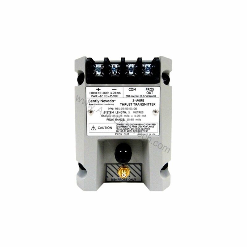
Introduction to the 991-06-70-03-CN Thrust Transmitter
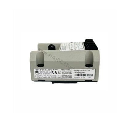
When axial shaft position monitoring is critical, the 991-06-70-03-CN from Bently Nevada provides a reliable solution. This probe vibration transmitter converts proximity probe signals into a standard 4-20 mA output, enabling seamless integration with control systems. Designed for axial thrust measurement, it helps protect rotating machinery from damaging axial displacement.
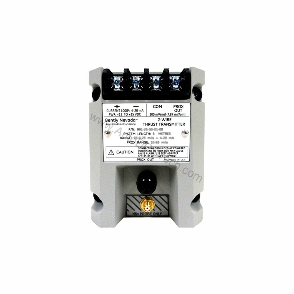
Key Features and Technical Specifications
The 991-06-70-03-CN is engineered for precision and durability. Below are the core specifications extracted from the manufacturer's data:
- Full-scale option: 0.6-0-0.6 mm (suitable for 25-0-25 mils current loop linear ranges).
- System length: 7.0 meters (23.0 feet) – includes probe and extension cable.
- Mounting: DIN rail with DIN clips and screws (mounting option 03).
- Output signal: 4-20 mA DC in a 2-wire configuration.
- Power requirement: +12 to +35 Vdc input at the transmitter terminal.
- Linear range: 0.25 to 1.65 mm for Prox Out.
- Accuracy: Within ±1.5% over the specified full-scale range (typical).
- Maximum loop resistance: 1,000 Ω including cable at 35 Vdc.
- Current limiting: 23 mA typical.
- Not OK/Signal Defeat: Output drops to less than 3.6 mA within 100 µs after a Not OK condition; restores within 0.1 seconds after removal.
- Operating temperature: -35°C to +85°C (-31°F to +185°F).
- Storage temperature: -51°C to +100°C (-60°F to +212°F).
- Weight: 0.43 kg (0.9 lbm).
- Agency approval: CN (country-specific approvals).
These specifications ensure accurate and reliable thrust measurement in demanding industrial environments.
Applications and Use Cases
The 991-06-70-03-CN is primarily used for axial position monitoring in rotating machinery such as turbines, compressors, and pumps. Its 4-20 mA output allows direct interface with PLCs, DCS, and SCADA systems. The compact DIN-rail mounting simplifies installation in control panels. With a linear range of 0.25 to 1.65 mm, it is suitable for applications requiring precise thrust measurement.
Installation and Setup
Mount the 991-06-70-03-CN on a standard DIN rail using the provided clips and screws. Ensure the system length of 7.0 meters is correctly routed to the probe. Connect the power supply (+12 to +35 Vdc) to the transmitter terminal. The 4-20 mA output should be wired in a 2-wire configuration to the monitoring system. Verify that the loop resistance does not exceed 1,000 Ω at 35 Vdc to maintain accuracy.
Maintenance and Reliability
Regular inspection of the transmitter and probe is recommended to ensure consistent performance. The operating temperature range of -35°C to +85°C allows use in harsh environments. The Not OK/Signal Defeat feature provides fast fault indication, minimizing downtime. For long-term reliability, follow the manufacturer's maintenance guidelines.
Comparison with Similar Products
Compared to standard vibration transmitters, the 991-06-70-03-CN offers a dedicated axial thrust measurement capability with a 0.6-0-0.6 mm full-scale range. Its 4-20 mA output is directly compatible with most industrial control systems. The DIN-rail mounting and country-specific approvals (CN) make it a versatile choice for global installations.
Availability
The 991-06-70-03-CN is available from AutoDCSTech. Please verify current lifecycle status and availability with AutoDCSTech before ordering.