Introduction to the 991-06-50-02-05 Thrust Transmitter
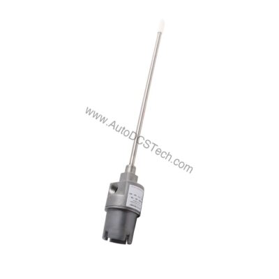
When axial shaft position drifts beyond safe limits, machinery can suffer catastrophic damage. The 991-06-50-02-05 from Bently Nevada provides a direct solution by converting proximity probe signals into a standardized 4-20 mA output. This thrust transmitter is engineered for continuous monitoring of axial displacement, helping you detect problems before they escalate.
Designed for DIN rail mounting, the 991-06-50-02-05 integrates easily into existing control panels. Its compact form factor and robust construction make it suitable for demanding industrial environments.
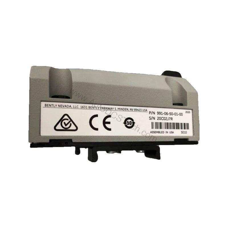
Key Features and Technical Specifications
The 991-06-50-02-05 offers a range of features that simplify installation and ensure accurate measurement. Below are the core specifications extracted from the official datasheet:
- Output Signal: 4-20 mA DC, two-wire configuration, over the specified full-scale range.
- Power Requirement: +12 to +35 Vdc input at the transmitter terminal.
- Linear Range: 0.25 to 1.65 mm for proximity output; suitable for 0.6-0-0.6 mm or 25-0-25 mils current loop linear ranges.
- Full-Scale Option: 0.6-0-0.6 mm (model 991).
- System Length: 5.0 meters (16.4 feet) cable.
- Mounting: DIN rail; bulkhead screw mounting option available.
- Operating Temperature: -35°C to +85°C (-31°F to +185°F).
- Storage Temperature: -51°C to +100°C (-60°F to +212°F).
- Weight: 0.43 kg (0.9 lbm).
- Loop Accuracy: Within ±1.5% over specified full scale (typical).
- Maximum Loop Resistance: 1,000 ohms including cable at 35 Vdc.
- Current Limiting: 23 mA typical.
One distinctive feature is the Not OK/Signal Defeat function. When a fault condition occurs, the output drops to less than 3.6 mA within 100 microseconds, alerting control systems immediately. This rapid response helps prevent undetected failures.
Applications and Use Cases
The 991-06-50-02-05 is specifically designed for axial thrust measurement in rotating machinery such as turbines, compressors, and large pumps. By monitoring axial position, it helps protect against thrust bearing wear and rotor misalignment.
In addition, the transmitter is suitable for use in hazardous areas. It carries CSA Division 2, ATEX Zone 0, ATEX Zone 2, and ABS maritime approvals, making it a versatile choice for offshore and onshore installations.
Because it accepts a single non-contacting 3300 NSv proximity probe and extension cable, the 991-06-50-02-05 simplifies retrofits and new installations alike.
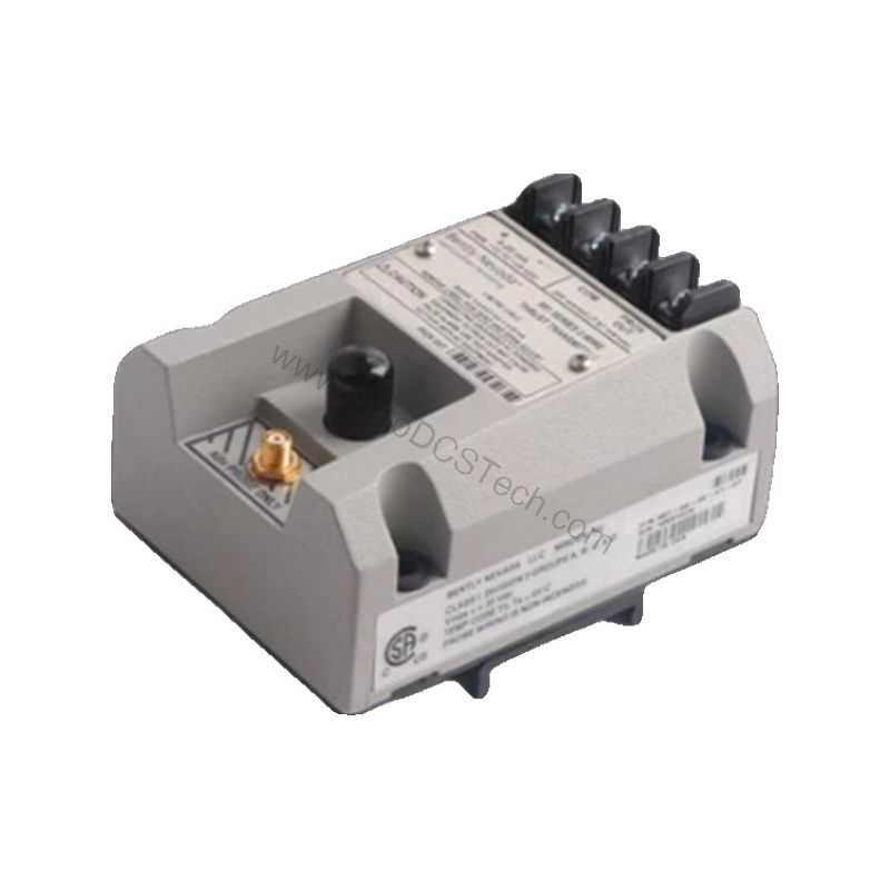
Installation and Setup
Mounting the 991-06-50-02-05 is straightforward. The unit snaps onto a standard DIN rail, and the bulkhead screw option provides additional stability in high-vibration environments. Ensure that the power supply provides +12 to +35 Vdc at the transmitter terminal.
Wire the output in a 2-wire loop configuration, connecting the 4-20 mA signal to your monitoring system. The non-interacting external zero and span adjustments allow fine calibration without affecting each other.
For accurate readings, position the proximity probe according to the specified linear range (0.25 to 1.65 mm). Verify that the system length of 5.0 meters matches your cable requirements.
Maintenance and Reliability
Regular inspection of the transmitter and probe is essential for long-term reliability. Check for loose connections, physical damage, and contamination on the probe face. The operating temperature range of -35°C to +85°C ensures performance in most industrial settings.
Because the 991-06-50-02-05 uses solid-state electronics, it requires minimal routine maintenance. However, periodic verification of the loop accuracy (within ±1.5%) is recommended to ensure measurement integrity.
Always follow the manufacturer's manual for detailed maintenance procedures. If you encounter issues, contact AutoDCSTech for support.
Troubleshooting Common Issues
If the output signal goes below 3.6 mA, the transmitter has detected a Not OK condition. This could be due to a faulty probe, cable break, or power supply issue. The signal restores within 0.1 seconds after the fault is removed.
Loop resistance exceeding 1,000 ohms can cause inaccurate readings. Check the total resistance of your loop, including cable, and ensure it stays within limits.
For zero and span drift, use the external adjustments to recalibrate. If problems persist, consult the official Bently Nevada documentation or contact AutoDCSTech.
Product Support and Availability
AutoDCSTech is your trusted supplier for the Bently Nevada 991-06-50-02-05 thrust transmitter. We maintain stock to meet your urgent requirements. Contact our team for pricing, lead times, and technical assistance.
Please verify current lifecycle status and availability with AutoDCSTech before ordering.