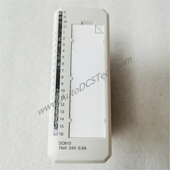
Introduction: Solving Process Voltage Supervision Challenges
In industrial automation, losing process voltage on a digital output group can cause undetected actuator failures, leading to costly downtime or unsafe conditions. When the voltage disappears, the module signals an error via the ModuleBus, allowing your control system to react immediately. This built-in diagnostic capability transforms a standard output module into a proactive monitoring tool.
Technical Specifications Breakdown
The DO810 offers 16 digital outputs organized into two individually isolated groups of eight channels. Each group includes a voltage supervision input that monitors the process voltage. Key parameters from the datasheet include:
- Output Voltage Range: 10 to 30 V DC (nominal 24 V DC)
- Maximum Continuous Output Current: 0.5 A per channel
- Output Load: Less than 0.4 Ω
- Current Limiting: Short-circuit proof, current-limited output
- Isolation: Groupwise isolated from ground
- Rated Insulation Voltage: 50 V
- Dielectric Test Voltage: 500 V AC
- Power Dissipation: Typ. 2.1 W
- Current Consumption +5 V Modulebus: 80 mA
These specs ensure robust performance in demanding environments. The short-circuit protection covers both ground and 30 V, while over-temperature protection limits output current under overload conditions. The module also features Output State Preset (OSP), which sets outputs to a predetermined state upon error detection, enhancing system safety.
Industry Applications
Manufacturing Assembly Lines: In automotive assembly, the DO810 controls pneumatic valves and actuators. The groupwise isolation allows one group to drive a critical clamping fixture while the other handles a conveyor section. If the process voltage fails on the conveyor group, the module immediately reports the fault, preventing incomplete assembly cycles.
Process Control Skids: For chemical dosing systems, the module's short-circuit and over-temperature protection safeguard against wiring faults. The OSP feature ensures that upon a communication error, outputs revert to a safe state, avoiding unintended chemical release.
Installation & Setup Guidance
Mount the DO810 on an S800 I/O base unit (MTU) such as TU810, TU812, TU814, or TU830. Use the keying code AA to ensure correct insertion. Connect field wiring to the MTU terminals respecting the group isolation: each group of eight outputs shares a common process voltage supervision input. Keep field cable length within 600 meters (656 yards) to maintain signal integrity. The module is IP20 rated, so install it in a clean, dry cabinet within the operating temperature range of 0 to +55 °C (+32 to +131 °F). For vertical mounting in compact MTU, the maximum ambient temperature is 40 °C (104 °F).
Maintenance & Reliability
The DO810 requires minimal routine care. Periodically inspect front panel LEDs for Fault (F), Run (R), Warning (W), OSP (O), and channel status indicators. Verify that process voltage supervision does not trigger false alarms due to loose wiring. The module's solid-state high-side drivers eliminate mechanical wear, so no contact cleaning is needed. Environmental protection includes corrosion protection per ISA-S71.04 G3 and pollution degree 2, making it suitable for moderate industrial atmospheres. To maximize reliability, keep the ambient temperature below 55 °C and ensure adequate airflow.
Compatibility & Integration
It is compatible with MTU units TU810, TU812, TU814, and TU830. The module supports standard 24 V DC current-sourcing outputs and includes diagnostic communication for process voltage supervision, module error, module warning, and channel error. It is CE marked and carries certifications for electrical safety (EN 61010-1, UL 61010-1), hazardous locations (C1 Div 2 cULus, C1 Zone 2 cULus, ATEX Zone 2), and marine applications (ABS, BV, DNV, LR).
Selection Guide & Purchasing Advice
Before ordering the DO810 (article number 3BSE008510R1), confirm your system's compatibility with the S800 mechanics and ModuleBus interface. Verify that your MTU supports the required number of channels and group isolation. The DO810 is a non-redundant, non-HART, non-SOE module, so for applications requiring redundancy or intrinsic safety, consider other S800 options. At AutoDCSTech, we stock the DO810 and can advise on lifecycle status and availability. Please verify current lifecycle status and availability with AutoDCSTech before ordering.
Troubleshooting & Common Issues
- Channel not switching: Check the process voltage supervision input. If the group voltage is missing, the module reports a channel error. Verify the field power supply is within 12–32 V DC.
- Overload condition: If the output current exceeds 0.5 A, the current limiting activates. Reduce the load or check for short circuits. The module will recover once the overload clears.
- OSP activation: If the module detects a ModuleBus communication error, it sets outputs to a predetermined state. Verify the bus connection and scan for network issues.
- Warning LED lit: This may indicate a process voltage warning or high temperature. Ensure ambient temperature is within limits and that the module has adequate ventilation.
Frequently Asked Questions
Q1: Can the DO810 drive 24 V DC solenoid valves directly?
Yes, each channel can source up to 0.5 A continuous, which is sufficient for most industrial solenoid valves. Ensure the valve's inrush current does not exceed the module's short-circuit protection threshold.
Q2: What does the OSP (Output State Preset) feature do?
OSP sets all outputs to an user-defined safe state when the module detects a communication error or a fault condition. This prevents uncontrolled actuator behavior during system faults.
Q3: Is the DO810 suitable for use in hazardous areas?
The module is certified for Class I Division 2 and Zone 2 hazardous locations (cULus and ATEX). It is not intrinsically safe, so it must be installed in an appropriate enclosure.
Q4: How do I interpret the front panel LEDs?
The module has LEDs for Fault (F), Run (R), Warning (W), OSP (O), and individual channel status (1–16). A steady green Run LED indicates normal operation. A red Fault LED signals a module error. The Warning LED indicates a non-critical condition such as process voltage loss.
Q5: What is the maximum cable length for field wiring?
The maximum field cable length is 600 meters (656 yards). For longer distances, consider using remote I/O or signal repeaters.
Please verify current lifecycle status and availability with AutoDCSTech before ordering.
Availability & Condition at AutoDCSTech
| Part Number | DO810 |
|---|---|
| Availability | In Stock |
| Condition | New |
| Warranty | One Year |
| Origin | Switzerland |