Technical Specifications Breakdown
Key parameters for the 1769-IF8 are listed below for quick reference:
| Feature | Specification |
|---|---|
| Module Type | Analog Input Module |
| Number of Inputs | 8 Inputs; Differential or Single Ended Inputs |
| Input Current Range | 0-21 mA |
| Current Signal Normal Ranges | 0-20 mA; 4-20 mA |
| Input Voltage Range | 0-10.5 VDC |
| Voltage Signal Normal Ranges | ±10V DC, 0…10V DC, 0…5V DC, 1…5V DC |
| Resolution | 16 bits (unipolar) 15 bits plus sign (bipolar) |
| Power Supply Distance Rating | 8 Modules |
| Working Voltage Rating | 30 Volts AC or 30 Volts DC |
| Shipping Weight | 2 pounds |
Industry Applications for the 1769-IF8
This analog input module is well-suited for process monitoring and control in industries such as manufacturing, water treatment, and material handling. For example, in a packaging line, the 1769-IF8 can read 4-20 mA signals from pressure transmitters to ensure proper sealing force. In a wastewater facility, it can acquire ±10 VDC signals from level sensors for tank monitoring. The module's eight channels allow multiple signals to be consolidated into one unit, reducing panel space and wiring complexity.
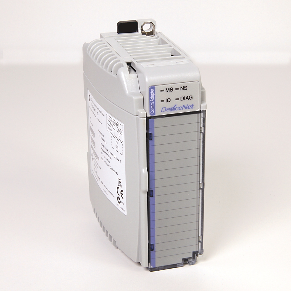
Installation and Setup Guidance
When installing the 1769-IF8, ensure it is placed within the power supply distance rating of 8 modules from the CompactLogix power supply to guarantee adequate backplane power. Use copper wire rated for 90 degrees Celsius, with a solid wire size of 22-14 AWG. For signal wiring, Belden 8761 shielded cable is recommended to minimize electrical noise. The module supports both differential and single-ended inputs; select the appropriate configuration based on your sensor type and noise environment. Always verify that the input signals are within the specified ranges: 0-21 mA for current and 0-10.5 VDC for voltage.
Maintenance and Reliability
To maintain reliable operation, periodically inspect the module's FAULT indicator light and review channel diagnostics for over- or under-range conditions. The module performs automatic self-diagnostics and can process alarms, helping you identify issues early. Keep the operating environment within 0 to 60 degrees Celsius and avoid condensation by maintaining relative humidity below 95%. The module's robust design includes compliance with standards such as C-UL, CE, and UL 508.
Selecting the Right Analog Input Module for Your Control System
When designing or upgrading an industrial control system, choosing the correct analog input module is critical for accurate data acquisition and reliable operation. The Allen-Bradley 1769-IF8 offers a robust solution for applications requiring multiple analog signal types. This module is part of the CompactLogix product line and is designed to interface with field devices transmitting 0-21 mA and ±10 VDC analog signals. It provides eight input channels that can be configured as differential or single-ended, giving you flexibility in wiring and signal conditioning.
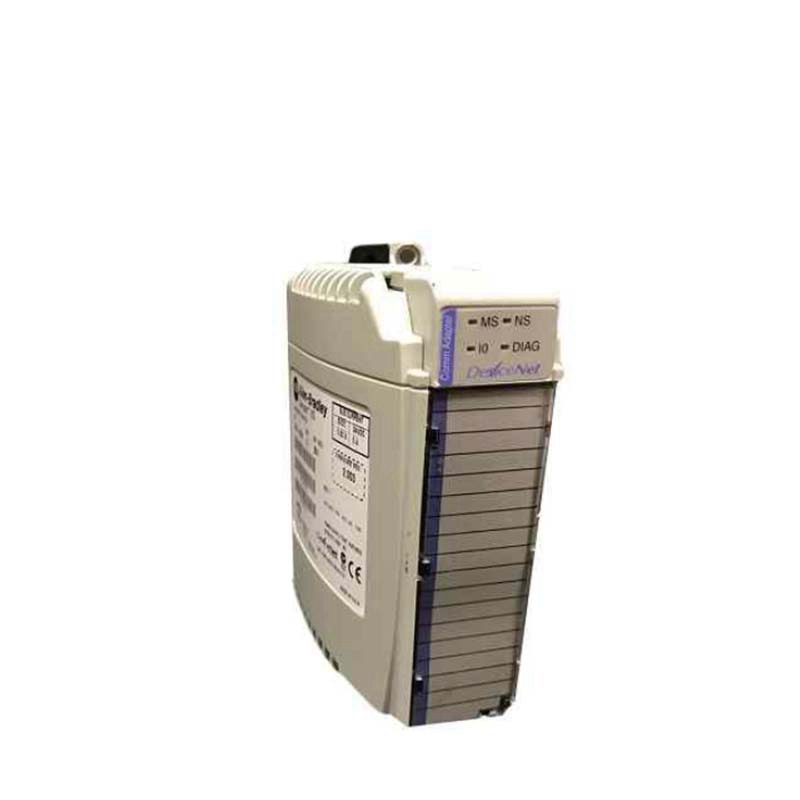
Compatibility and Integration
The 1769-IF8 is compatible with MicroLogix 1500 and CompactLogix controllers, making it a versatile choice for mixed-platform systems. It uses the Delta-Sigma analog-to-digital conversion method, providing 16-bit unipolar or 15-bit plus sign bipolar resolution. The module communicates over the backplane and stores converted data in the processor's memory as binary values, which can be scaled using instructions like Scale for engineering units, PID, percent range, or raw data.
Selection Guide and Purchasing Advice
When selecting an analog input module, consider the number of channels and signal types required. The 1769-IF8 offers eight inputs with both current and voltage ranges, making it a flexible option for many applications. If you need a replacement terminal block, the 1769-RTBN18 is compatible. For purchasing, contact AutoDCSTech to verify current lifecycle status and availability. They can provide guidance on whether this module is the right fit for your system.
Troubleshooting and Common Issues
Common issues with analog input modules include signal noise and incorrect readings. Check that wiring uses shielded cable and that the shield is properly grounded. Verify that the input signal is within the module's full range: 0-21 mA for current or ±10.5 VDC for voltage. If the FAULT indicator is lit, review the channel diagnostics for over- or under-range conditions. The module's bit reporting can help pinpoint which channel is experiencing a problem.
Availability & Condition at AutoDCSTech
| Part Number | 1769-IF8 |
|---|---|
| Availability | In Stock |
| Condition | New |
| Warranty | One Year |
| Origin | US |