Technical Specifications Breakdown
Key parameters for the 1771-ID are listed below for quick reference:
| Feature | Specification |
|---|---|
| Module Type | Individually isolated discrete output module |
| Number of Inputs | Six (6) inputs |
| Operating Voltage Range | 92 - 138VAC / 92-138 VDC |
| AC Input Frequency | 47-63 Hz |
| Nominal Input Current | 8mA @ 120V ac; 8mA @ 120V dc |
| Input Signal Delay (AC) | 24+10ms, on or off for ac |
| Input Signal Delay (DC On) | 10+4ms for turning on dc |
| Input Signal Delay (DC Off) | 20+9ms for turning off dc |
| Power Dissipation | 0.4-4.4 Watts |
| Thermal Dissipation | 1.3 BTU/hr-15.0 BTU/hr |
| Backplane Current | 74 Miliamperes |
| Max Off-State Current | 1.7 Miliamperes (AC and DC) |
| Dimensions | 3.5 x 6.5 x 2.0 in (89 x 165 x 51 mm) |
Industry Applications
The 1771-ID is engineered for isolated-circuit multi-phase applications. Common use cases include:
- Float switches: Detecting liquid levels in tanks with individual channel isolation to prevent cross-talk.
- Limit switches: Monitoring mechanical positions in conveyor systems, where each input can be wired to a different voltage source.
- Pushbuttons and selector switches: Providing clean signal detection in control panels, even in electrically noisy environments.
By using individual isolation, this module reduces the risk of ground loops and improves system reliability, directly contributing to lower operational costs and reduced troubleshooting time.
Installation & Setup Guidance
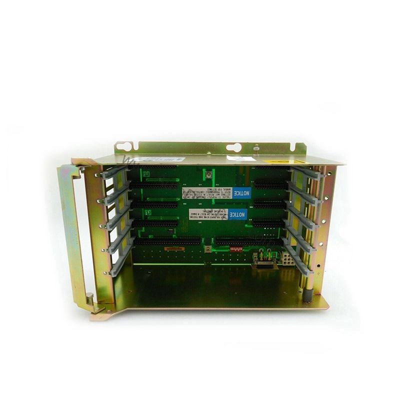
Mount the 1771-ID into any 1771 I/O chassis, occupying a single slot. Use the included 1771-WD Field Wiring Arm for modular wiring connections. Ensure keying positions are set between 4 and 6, and between 28 and 30, to prevent incorrect module insertion. Terminate input devices using 14 Gauge stranded or solid copper wire with 3/64 maximum insulation. Tighten the wiring arm screws to 7-9 inch-pounds. Before powering up, verify that the total backplane current load (74 mA per module) does not exceed the chassis power supply capacity.
Maintenance & Reliability
Periodically inspect the module for signs of dust or corrosion on the wiring arm connections. Operate within the specified voltage range (92-138VAC/VDC) to avoid damage. The module's input filtering helps suppress voltage transients from electrical noise and contact bounce, enhancing long-term reliability. No internal adjustments are required; focus on maintaining clean connections and proper environmental conditions.
Compatibility & Integration
The 1771-WD field wiring arm is the standard connection interface. Ensure your system's backplane can supply the required 74 mA per module.
Selection Guide & Purchasing Advice
When selecting the 1771-ID, confirm that your application requires six individually isolated inputs with dual AC/DC capability. If you need more channels or different voltage ratings, explore other 1771 series modules. For genuine Allen-Bradley parts and expert support, consider AutoDCSTech as your sourcing partner. They offer verified inventory and technical guidance to match your specific needs.
Troubleshooting & Common Issues
- No input signal: Verify the input voltage is within 92-138VAC or 92-138VDC. Check wiring arm connections and screw torque (7-9 inch-pounds).
- False triggering: Inspect for excessive electrical noise; the module's filtering (24+10ms AC delay) should mitigate most transients, but ensure proper grounding.
- Module not recognized: Confirm keying positions and that the chassis backplane is not overloaded. Measure backplane current draw to ensure it does not exceed supply limits.
Availability & Condition at AutoDCSTech
| Part Number | 1771-ID |
|---|---|
| Availability | In Stock |
| Condition | New |
| Warranty | One Year |
| Origin | US |