Technical Specifications Breakdown
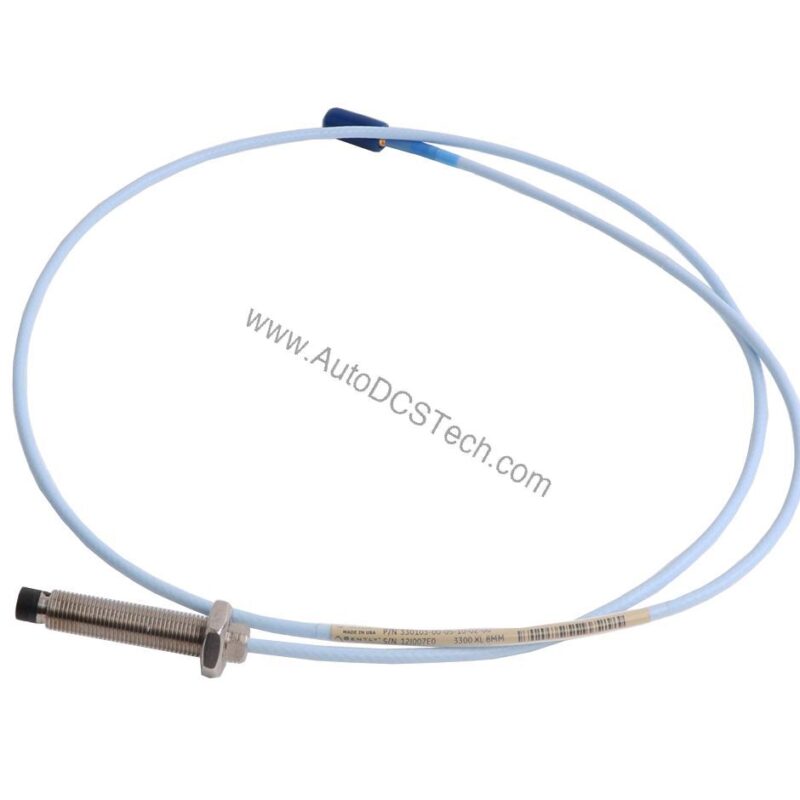
Key parameters for the 330103-00-04-05-01-00 are listed below for quick reference:
| Feature | Specification |
|---|---|
| Product Type | 3300 XL 8 mm Proximity Probe, Metric |
| Thread Size | M10 x 1 |
| Unthreaded Length | 0 mm |
| Overall Case Length | 40 mm |
| Total Length | 0.5 meter (1.6 feet) |
| Connector | Miniature coaxial ClickLoc with connector protector, standard cable |
| Probe Tip Material | Polyphenylene sulfide (PPS) |
| Probe Case Material | AISI 303 or 304 stainless steel (SST) |
| Linear Range | 2 mm (80 mils) |
| Recommended Gap Setting (Radial Vibration) | -9 Vdc [approximately 1.27 mm (50 mils)] |
| Operating Temperature (Standard Probe) | -52°C to +177°C (-62°F to +350°F) |
Industry Applications and Performance Considerations
Steam Turbine Bearing Monitoring
In high-speed steam turbines, the probe’s 2 mm linear range and -9 Vdc recommended gap setting provide reliable radial vibration data. The PPS tip withstands temperatures up to +177°C standard, while the stainless steel case resists corrosion from steam and oil mist. The 0.5 m cable with ClickLoc connector simplifies field replacement without compromising signal integrity.
Centrifugal Compressor Shaft Position
For compressors handling hazardous gases, the probe’s intrinsic safety approvals (Class I, Zone 0: AEx/Ex ia IIC T5...T1 Ga) when installed with appropriate zener barriers or galvanic isolators allow installation in explosive environments. The 0.25 mm to 2.3 mm measurement range captures both static position and dynamic vibration.
Pump Health Monitoring in Refineries
Pumps operating in high-humidity conditions benefit from the probe’s less than 3% change in Average Scale Factor after 56 days at 93% humidity per IEC 68-2-3. The M10 x 1 thread with 15 mm maximum engagement ensures secure mounting in standard pump bearing housings.
Installation and Setup Guidance
When installing the 330103-00-04-05-01-00, ensure the probe tip is clean and the target surface is smooth. Use the recommended field wiring of 0.2 to 1.5 mm² (16 to 24 AWG) three-conductor shielded triad cable. Maximum cable length between the probe and monitor is 305 meters (1,000 feet). For radial vibration applications, set the initial gap to approximately -9 Vdc (1.27 mm). Always verify the probe resistance (RPROBE) of 7.45 ± 0.50 Ω at 1.0 m length before final installation.
Maintenance and Reliability
Inspect the probe cable and connector periodically for signs of wear or damage. The probe is designed to seal differential pressure between tip and case using a Viton O-ring. Avoid exposing the probe to temperatures below -34°C (-30°F) to prevent premature pressure seal failure. For extended temperature range applications, the probe tip can operate up to +218°C and the cable up to +260°C.
Selecting the Right Proximity Probe for Reliable Vibration Monitoring
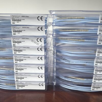
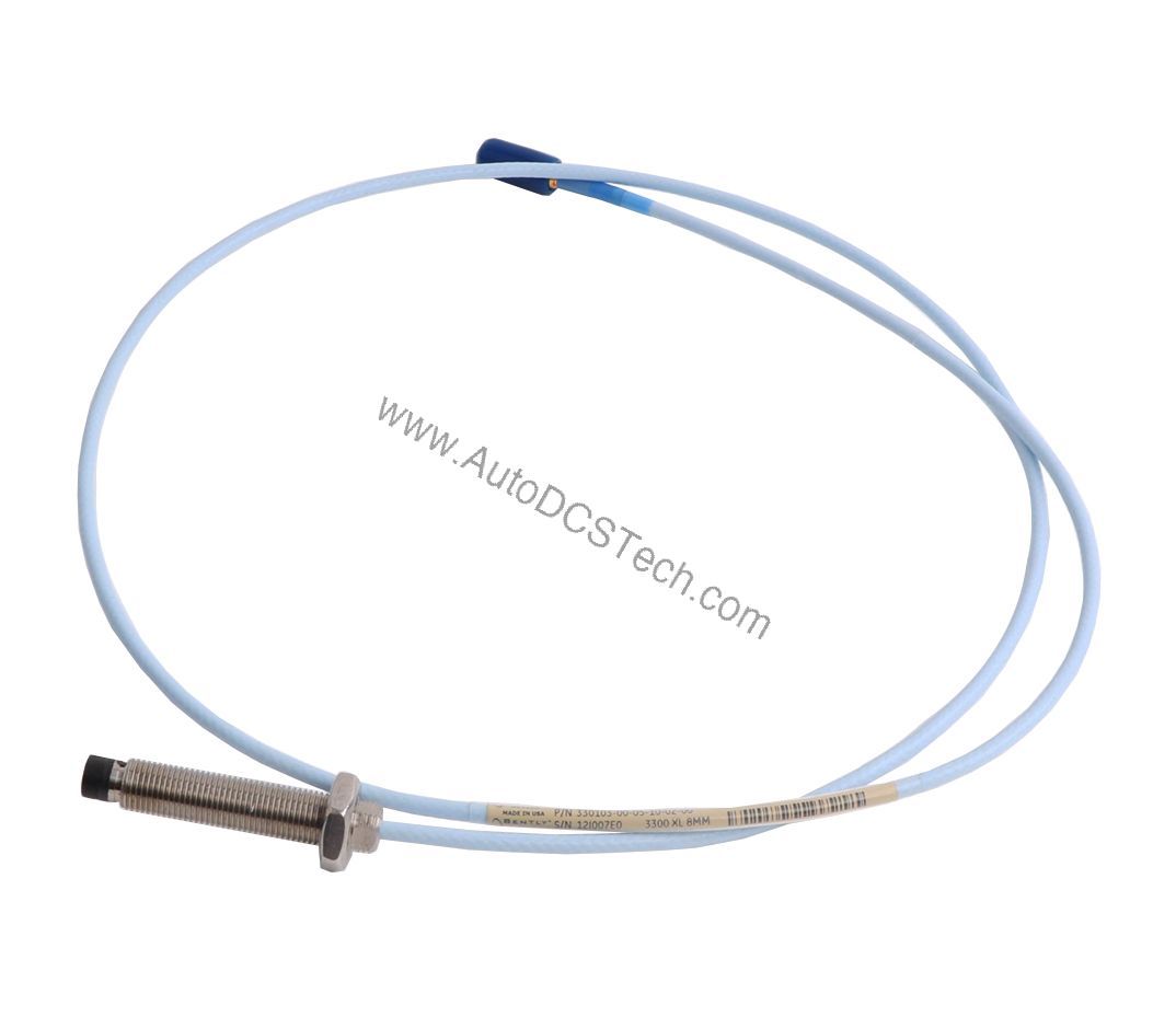
The Bently Nevada 330103-00-04-05-01-00 is a 3300 XL 8 mm proximity probe designed for permanent installation in critical applications such as steam turbines, compressors, and pumps. This article helps you evaluate this probe against your specific requirements, focusing on its key specifications and real-world performance.
Compatibility and Integration
This probe is part of the 3300 XL system and works with Bently Nevada Proximitor sensors and monitors. When used with intrinsically safe zener barriers per drawing 141092 or galvanic isolators, it achieves Class I, Zone 0 approval. For non-incendive installations, follow drawing 140979 for Class I, Zone 2 applications.
Selection Guide and Purchasing Advice
When selecting the 330103-00-04-05-01-00, verify your required thread size (M10 x 1), cable length (0.5 m), and agency approvals. This probe does not include armor and is suited for standard industrial environments. For custom pressure testing or special requirements, contact your supplier. AutoDCSTech stocks this probe and can advise on availability and lifecycle status.
Troubleshooting and Common Issues
If the probe output is erratic, check the cable for damage and verify the connector is fully seated. Confirm the target material is conductive and the gap is within the linear range (0.25 to 2.3 mm). Measure the probe DC resistance at the connector; a reading outside 7.45 ± 0.50 Ω may indicate a damaged probe. For signal roll-off at high frequencies, review the frequency response graphs for your field wiring length.
Availability & Condition at AutoDCSTech
| Part Number | 330103-00-04-05-01-00 |
|---|---|
| Availability | In Stock |
| Condition | New |
| Warranty | One Year |
| Origin | US |