Technical Specifications Breakdown
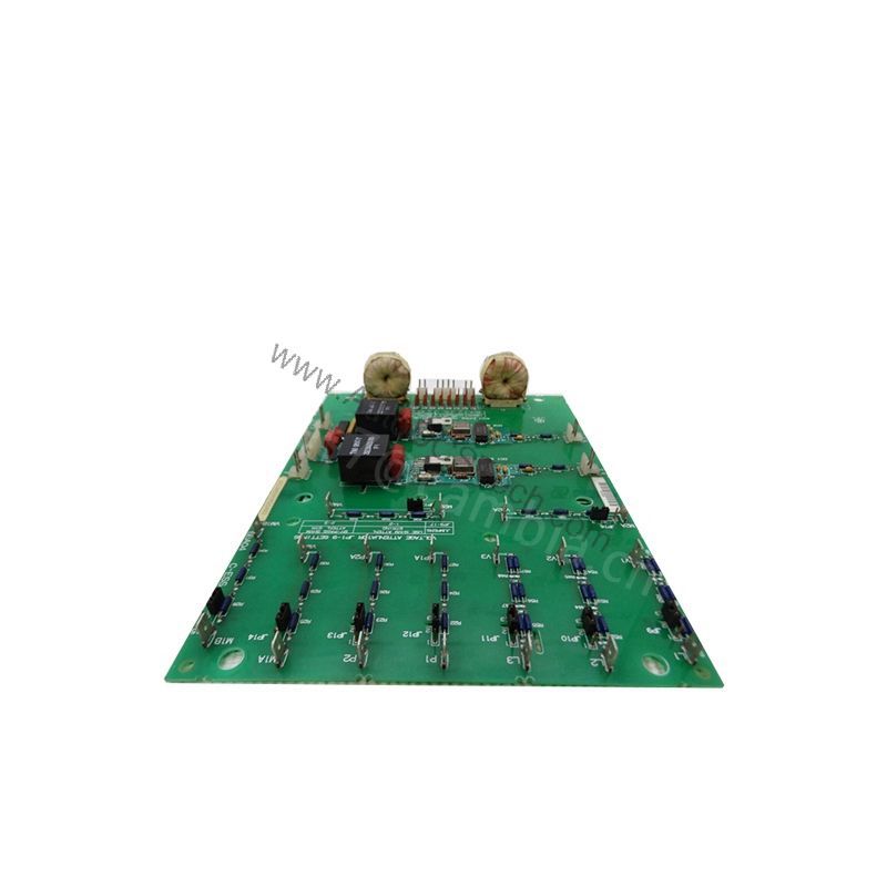
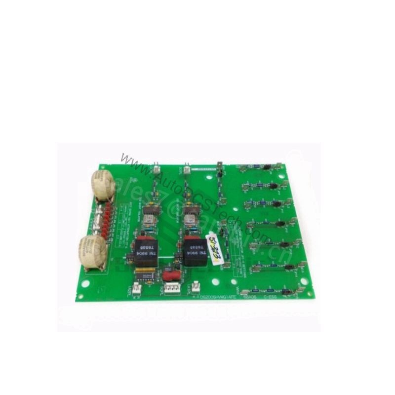
Key parameters for the 531X111PSHAPG2 are listed below for quick reference:
| Feature | Specification |
|---|---|
| Power Supply Outputs | 5 VDC, 15 VDC, 24 VDC |
| Pulse Transformer | For motor field circuitry |
| Relay Points | 3 onboard |
| Potentiometers | 3 (for current/feedback regulation) |
| Jumpers | 5 (for calibration) |
| Board Version | G3 (MOVs for AC line not placed on board) |
Industry Applications and Operational ROI
This terminal board relay card is a cost-effective solution for maintaining legacy DC drive systems in industries like metal processing, paper mills, and material handling. By providing three selectable power supplies (5 VDC, 15 VDC, 24 VDC) and an integrated pulse transformer for motor field control, it reduces the need for multiple separate modules. This consolidation lowers spare parts inventory costs and simplifies troubleshooting. The three onboard relays allow flexible control of auxiliary functions, while the potentiometers and jumpers enable precise current and feedback calibration, minimizing downtime during setup.
Installation and Setup Guidance
Installation of the GE 531X111PSHAPG2 must be performed only by qualified personnel familiar with high-voltage drive systems. Before beginning, inspect the area around the drive for moisture, trip hazards (tools, cables), and ensure only grounded extension cords are used. Verify that all 3-phase power cabling is in good condition and that the emergency shut-off is accessible and functional. Never work alone; have a second person nearby who knows emergency procedures. The board is a replacement unit and should be handled with standard ESD precautions.
Maintenance and Reliability
Periodically inspect the board for signs of dust accumulation, loose connections, or component stress. Because the drive contains high voltages and moving parts, only trained individuals should perform maintenance. Ensure the environment remains dry and free of conductive debris. The G3 version does not have MOVs on the board for AC line protection, so external surge protection may be considered based on site conditions. Regular calibration checks using the onboard potentiometers and jumpers help maintain accurate current and feedback signals.
Compatibility and Integration
The 531X111PSHAPG2 is designed for GE DC drive control systems within the 531X series. It integrates directly as a terminal board relay card, supplying power and pulse transformer functionality to the motor field circuitry. It is not a standalone drive but a critical support board. For integration, verify that your drive system accepts this G3 revision board and that the three relay outputs match your control logic requirements.
Selection Guide and Purchasing Advice
When selecting a replacement or spare for your GE drive system, confirm that the part number 531X111PSHAPG2 matches your existing board revision. AutoDCSTech stocks this board to support your legacy equipment needs. Please verify current lifecycle status and availability with AutoDCSTech before ordering. Our team can help you confirm compatibility with your specific drive model.
Troubleshooting and Common Issues
If the drive fails to power up or the motor field does not energize, first check that the board is seated correctly and that all connectors are secure. Measure the output voltages at the test points: they should be 5 VDC, 15 VDC, and 24 VDC as specified. If voltages are absent or incorrect, inspect the input power to the board. For erratic motor field behavior, verify the pulse transformer connections. Use the three potentiometers to adjust current and feedback signals per your drive's service manual. If issues persist, consult a qualified service technician.
Availability & Condition at AutoDCSTech
| Part Number | 531X111PSHAPG2 |
|---|---|
| Availability | In Stock |
| Condition | New |
| Warranty | One Year |
| Origin | US |