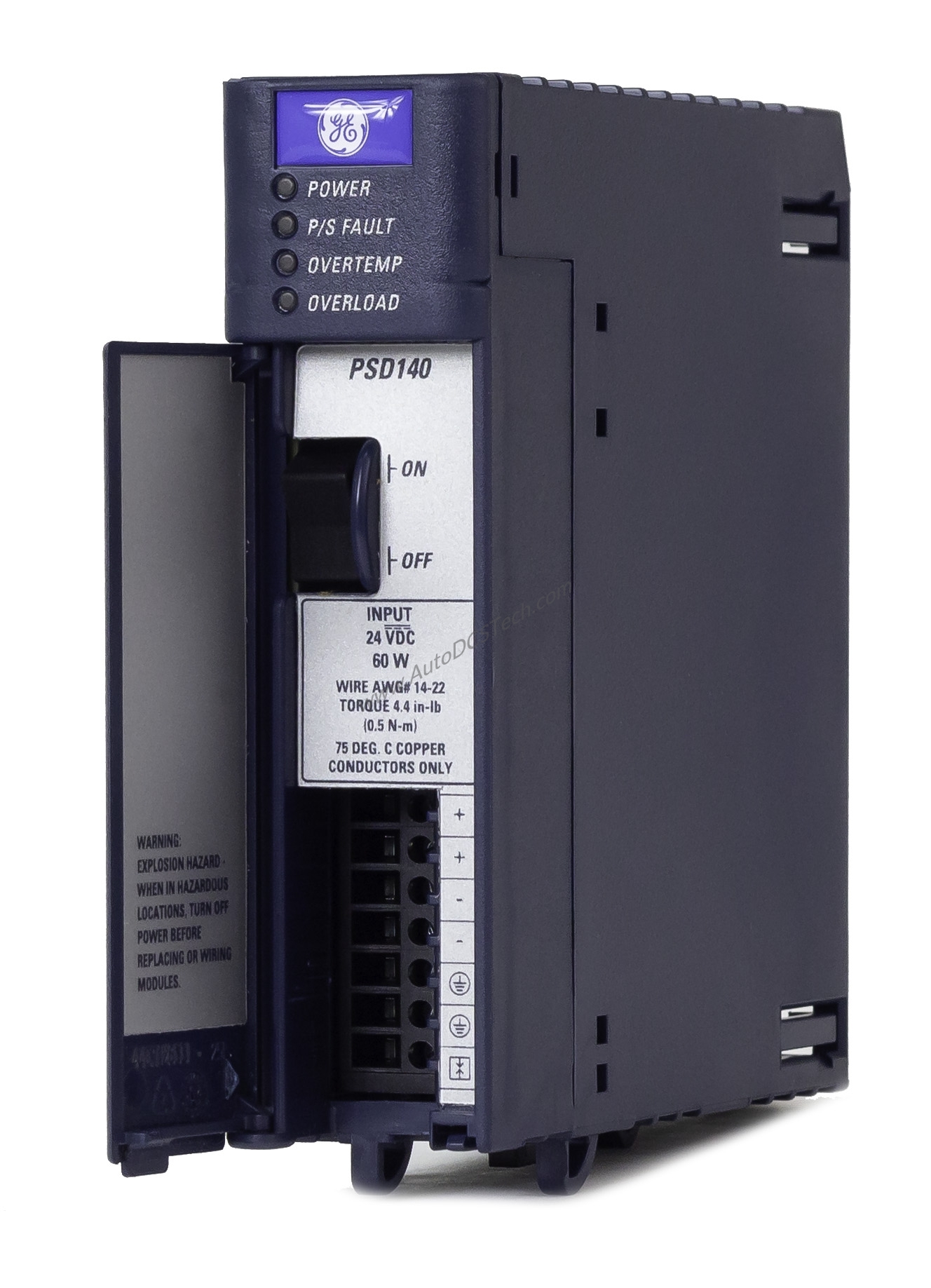
Technical Specifications Breakdown
The IC695PSD140 offers three independent outputs: 5.1 VDC (0 to 6 Amps), 3.3 VDC (0 to 9 Amps), and 24 VDC (0 to 1.6 Amps). Each output has a defined voltage tolerance: 5.0 VDC to 5.2 VDC for the 5.1 VDC rail, 3.1 VDC to 3.5 VDC for the 3.3 VDC rail, and 19.2 VDC to 28.8 VDC for the 24 VDC rail. Total output power is 40 Watts maximum, with individual limits of 30 Watts for both 5.1 VDC and 3.3 VDC outputs. The module also features 150 mV ripple and noise, ensuring clean power delivery. Four LED indicators (Power, P/S Fault, Overtemperature, Overload) provide real-time status monitoring.
Industry Applications
In manufacturing plants, power supply failures can halt production lines. This configuration enables load sharing and redundancy, so if one module fails, others maintain power. Typical applications include continuous process control, discrete manufacturing, and critical infrastructure where uptime is paramount. The 24 VDC output powers relay modules and field devices, while the 5.1 VDC and 3.3 VDC rails supply logic circuits.
Installation & Setup Guidance
Mounting the IC695PSD140 is straightforward: install it into an RX3i universal backplane. The module occupies two slots and requires no jumper or DIP switch configuration. Use #14 to 22 AWG wire for terminal connections, with a maximum terminal current of 6 Amps. The front-panel On/Off switch allows manual control. For redundancy setups, ensure all power supplies connect to the same power source and keep the minimum number of units powered on to qualify the system.
Maintenance & Reliability
Routine inspection of the IC695PSD140 focuses on verifying LED indicators and checking for overheating or overload conditions. The overtemperature and overload LEDs alert operators to potential issues. Since the module has no isolation, ensure proper grounding and follow manufacturer guidelines for periodic testing. In load-sharing architectures, avoid accidentally turning off the On/Off switch, as this can disrupt system power.
What Is the IC695PSD140?
This PACSystems RX3i power supply module, manufactured by Emerson Automation (formerly GE Intelligent Platforms), delivers stable DC power for critical automation tasks. It accepts an input voltage range of 18 to 30 VDC and supplies up to 60 Watts at full load. The module supports load sharing and redundancy, ensuring uninterrupted operation in demanding industrial environments.
Compatibility & Integration
It is compatible with all RX3i I/O modules, but cannot be used with IC695PSD040 or IC695PSA040 modules in redundant or increased capacity modes. Up to four PSD140 units can be daisy-chained for expanded power capacity or redundancy.
Buying Guide & Purchasing Advice
Before ordering, verify that your system uses an RX3i universal backplane and that the input voltage matches your facility supply (18 to 30 VDC). Contact AutoDCSTech for current availability and lifecycle status. We stock genuine GE Fanuc parts and offer competitive pricing for industrial automation needs.
Availability & Condition at AutoDCSTech
| Part Number | IC695PSD140 |
|---|---|
| Availability | In Stock |
| Condition | New |
| Warranty | One Year |
| Origin | US |