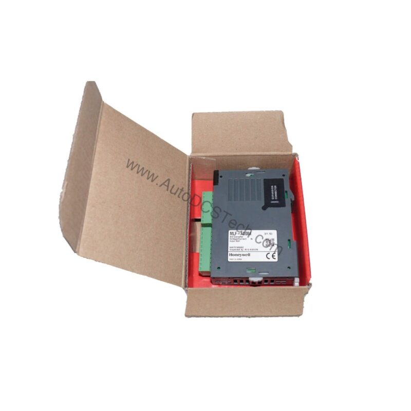
Technical Specifications Breakdown
Key parameters for the MLF-AD08A are listed below for quick reference:
| Feature | Specification |
|---|---|
| Product Type | Analog Input, Current/Voltage |
| Channels | 8 channels/module |
| Voltage Input Ranges | DC 1~5 V, DC 0~5 V, DC 0~10 V |
| Current Input Ranges | DC 4~20 mA, DC 0~20 mA |
| Input Resistance (Voltage) | 250 MΩ min. |
| Input Resistance (Current) | 250 Ω |
| Max. Conversion Speed | 1.5 ms/channel |
| Absolute Max. Input | ±15 V, ±25 mA |
| I/O Points Occupied | Fixed point assignment: 64 |
| Insulation Method | Photo-coupler insulation between I/O terminal and power supply |
| Current Consumption | DC5V 105mA, DC24V 85mA |
| Weight | 70g |
Industry Applications
This module is well-suited for continuous process industries where precise monitoring of analog signals is essential. In a chemical plant, for example, the MLF-AD08A can acquire 4–20 mA signals from pressure transmitters across multiple process lines. The 1.5 ms per channel conversion speed allows fast updates, enabling timely control actions.
In a water treatment facility, the module can handle both 0–10 V level sensors and 0–20 mA flow meters simultaneously. The fixed 64-point I/O assignment simplifies system configuration, reducing engineering time during commissioning.
From a cost-benefit perspective, using a single 8-channel module reduces per-point cost and panel space compared to multiple 4-channel units. The photo-coupler isolation protects the CPU from field transients, minimizing the risk of costly board failures.
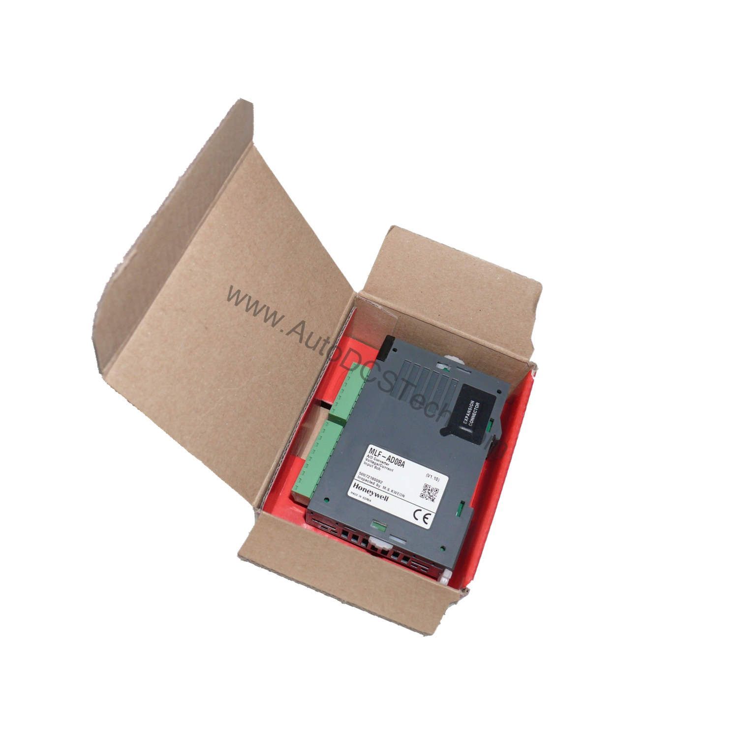
Installation & Setup Guidance
When installing the MLF-AD08A, ensure the module is securely mounted in the designated slot of the I/O rack. Verify that the backplane connector is clean and aligned before locking the module in place. For field wiring, use shielded twisted-pair cables for analog signals to reduce electromagnetic interference. Terminate the shield at the ground point specified by your system design.
Before powering up, double-check that the input signal ranges match your sensor outputs. For voltage inputs, confirm the input resistance (250 MΩ min.) is adequate for your source impedance. For current inputs, the 250 Ω input resistance is standard for most transmitters. Ensure the absolute maximum input ratings (±15 V, ±25 mA) are not exceeded to avoid damage.
After wiring, apply power and verify that the module's status indicators (if present) show normal operation. Use the PLC programming software to monitor raw digital values and compare them with expected readings from a known signal source. This validation step helps catch wiring errors early.
Maintenance & Reliability
Periodic inspection of the module and its connections is recommended to ensure long-term reliability. Check that all terminal screws are tight and that no corrosion or moisture is present on the connectors. Keep the enclosure clean and within the specified operating environment.
Because the module uses photo-coupler isolation, it is inherently robust against ground loops and common-mode noise. However, it is still good practice to periodically verify that the field wiring insulation is intact and that no cable damage has occurred.
If the module is part of a safety-critical loop, follow your facility's preventive maintenance schedule for calibration checks. Use a calibrated signal source to verify accuracy at multiple points within the input range. This proactive approach helps detect drift before it affects process quality.
Analog Input Precision for Demanding Processes
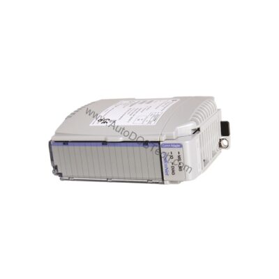
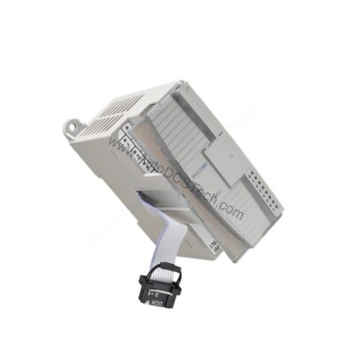
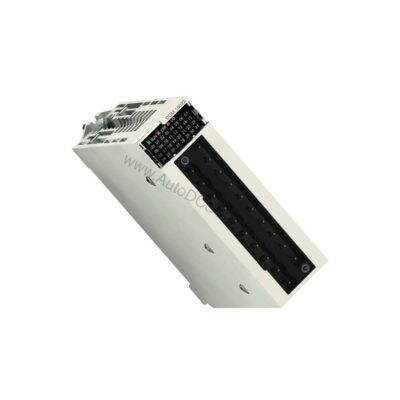
For maintenance engineers, signal integrity is the backbone of process control. The Honeywell MLF-AD08A analog input module delivers reliable 8-channel data acquisition for both current and voltage signals, ensuring your PLC sees accurate field conditions. With its robust design and clear signal mapping, this module simplifies troubleshooting and reduces downtime in critical applications.
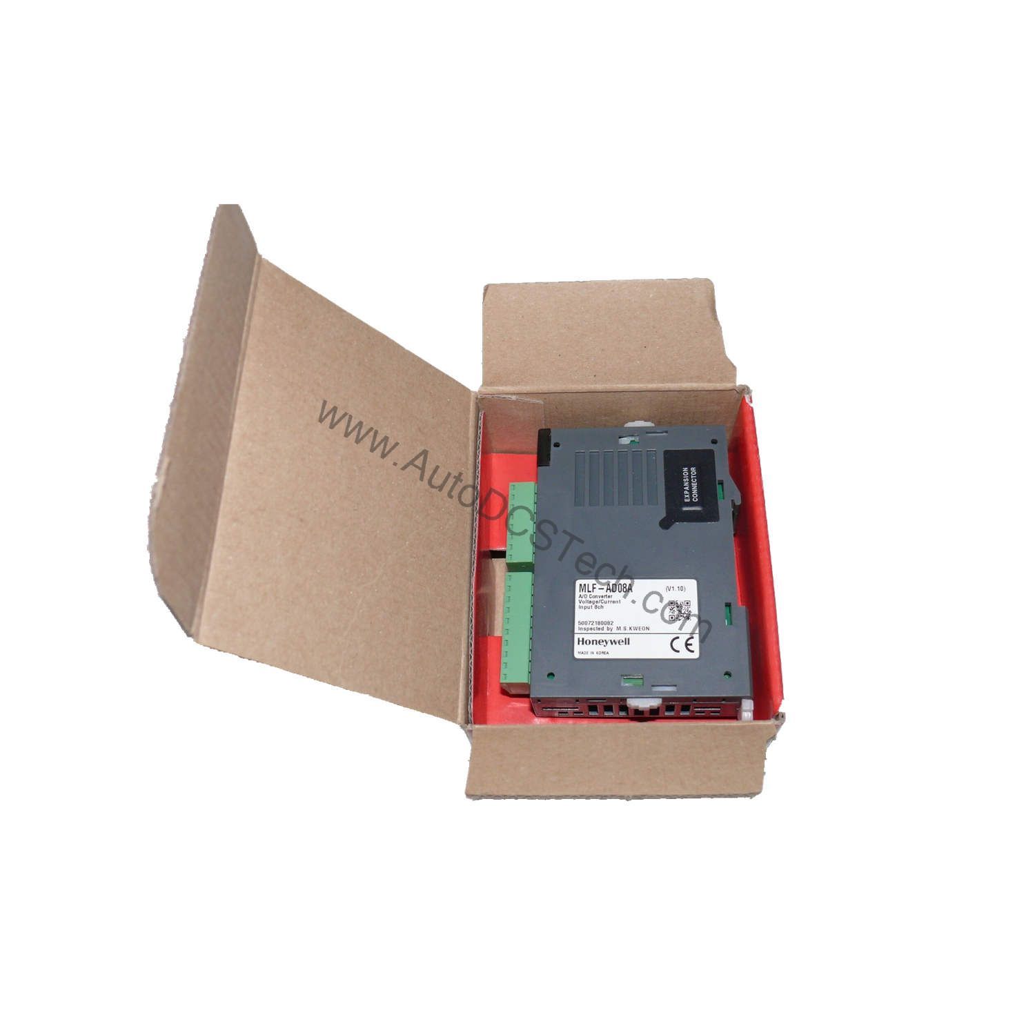
Compatibility & Integration
The MLF-AD08A is designed for Honeywell control systems, but its standard analog input ranges (DC 1–5 V, 0–5 V, 0–10 V, 4–20 mA, 0–20 mA) make it compatible with a wide variety of industrial sensors and transmitters.
When integrating this module into an existing system, confirm that the backplane and power supply can handle the additional current consumption (DC5V 105mA, DC24V 85mA). Also, verify that the system's firmware supports this module revision.
Selection Guide & Purchasing Advice
When selecting the MLF-AD08A, consider the number of analog channels you need and the signal types present in your application. If you require more than 8 channels, multiple modules can be installed, but remember that each module occupies 64 I/O points. Plan your I/O budget accordingly.
For purchasing, AutoDCSTech offers genuine Honeywell modules with reliable availability. Contact AutoDCSTech to confirm current lifecycle status and availability before ordering. Their technical team can assist with compatibility questions and expedite your procurement process.
Troubleshooting & Common Issues
If the module is not reading signals correctly, first verify that the field wiring is correct and that the sensor is powered. Use a multimeter to check the signal at the module terminals. If the signal is present but the digital value is incorrect, review the scaling settings in your PLC program.
Another common issue is ground loops causing noisy readings. Ensure that the shield is grounded at only one end, preferably at the control panel. If the module does not power up, check the backplane connection and the power supply voltages (DC5V and DC24V) at the rack.
If the module appears faulty, inspect the terminal block for signs of overvoltage or overcurrent damage. Remember that the absolute maximum input is ±15 V and ±25 mA; exceeding these values can permanently damage the input circuitry. In such cases, replace the module with a new one from AutoDCSTech.
Availability & Condition at AutoDCSTech
| Part Number | MLF-AD08A |
|---|---|
| Availability | In Stock |
| Condition | New |
| Warranty | One Year |
| Origin | US |