Technical Specifications Breakdown
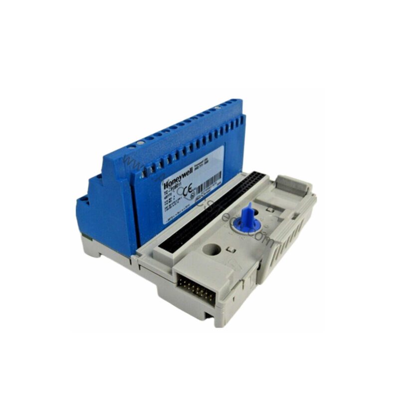
Key parameters for the TC-PTBC11 are listed below for quick reference:
| Feature | Specification |
|---|---|
| Brand | Honeywell |
| Part Number | TC-PTBC11 |
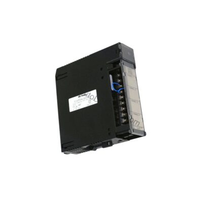
| Product Type | Terminal Base with Screw Clamps |
| I/O Capacity | 1 module per terminal base – mechanically keyed before wiring |
| Input Voltage Rating (Intrinsically Safe Power Supply Channel) | Ui 10Vdc, Ii 2.5A, Li = Negligible, Ci 1nF |
| Terminals | 52 screw terminals: 1 row of 16 and 2 rows of 18 |
| Terminal Assignments | Power Supply: +34, -35, +50, -51 (Use +50 and –51 to “daisy chain” power to another Terminal Base.) |
| No Connection | 36, 49 – Make no connection to these terminals. |
| Input/Output | Assignments made per I/O module – See individual I/O module specifications. Ui ≤ 30Vdc, Ii ≤ 100mA, Li = Negligible, Ci ≤ 1nF |
| Internal Bus (Backplane) | Vendor-Specific Bus – 16-pole plug SL2 and 16-pole socket BL2: Ui ≤ 10Vdc, Ii ≤ 400mA, Li = Negligible, Ci ≤ 1nF |
| Galvanic Isolation (Per DIN EN 50 020) | Backplane Bus / I/O Modules, I/O Modules / Power Supply. Isolation Voltage Determined by the I/O module used. |
| Operating Temperature | –20°C to 70°C (–4°F to 158°F or 253K to 343K) |
| Storage Temperature | –20°C to 100°C (–4°F to 212°F or 253K to 373K) |
| Maximum Relative Humidity | 95%, non-condensing |
| Pollution Gas Test | Test Level G3, according to ISA-S71.04-1985 |
| Shock Test | 15g peak 11ms duration |
| Vibration Test | 2g @ 10Hz to 500Hz, according to IEC 68-2-6 |
| Protection Class | IP20 (For installation in the field, a separate housing with protection class IP54 or better is required.) |
| Weight | 0.228 kg (0.50 lb) |
| Dimensions (H x W x D) | Millimeters: 92 x 94 x 94 (With I/O module installed); Inches: 3.6 x 3.7 x 3.7 |
| Wire Cross Section | 0.2 to 2.5mm (0.0003 to 0.004in2), with two cables maximum 2 x 1.5mm (0.002in2) per terminal |
| Terminal Screws | M3, screwdriver 3.5mm (0.14in) x 0.5mm (0.02in) |
| Conformity to Standards | According to DIN EN 50014: 1992, DIN EN 50020: 1997, DIN EN 50284: 1997 |
| Climatic Conditions | according to DIN IEC 721 |
| E.M. Compatibility | according to DIN EN 50081-2, DIN EN 50082-2, NAMUR NE 21 |
| CE Conformity (Europe) | To achieve EMC protection class, must mount in a cabinet with a copper seal and install ferrites on power supply and ControlNet Coax cables. |
| Classifications | CENELEC (Europe): II 2G EEx ia IIC T4 |
| Agency Certification | Marked for all applicable directives; DMT 98 ATEX E 036 U |
Installation and Setup Guidance
Before wiring, verify that the I/O module is mechanically keyed to the base to prevent mismatched installation. Use the power terminals +34, -35 for the supply, and +50, -51 to daisy-chain power to adjacent bases. Leave terminals 36 and 49 unconnected. Ensure that the wire cross-section is within 0.2 to 2.5 mm², and if using two cables per terminal, each must be no larger than 1.5 mm². Tighten the M3 screws with a 3.5mm x 0.5mm screwdriver. For field mounting, enclose the base in a housing with at least IP54 protection.
Maintenance and Reliability
Periodically inspect the terminal base for loose screws and signs of corrosion, especially in humid or corrosive environments. The unit is rated for 95% non-condensing humidity and can withstand 15g shocks and 2g vibration from 10Hz to 500Hz. Clean the base with a dry cloth only; do not use solvents. Verify that the copper seal and ferrites are in place if CE EMC compliance is required.
Field Termination Challenges in Hazardous Areas
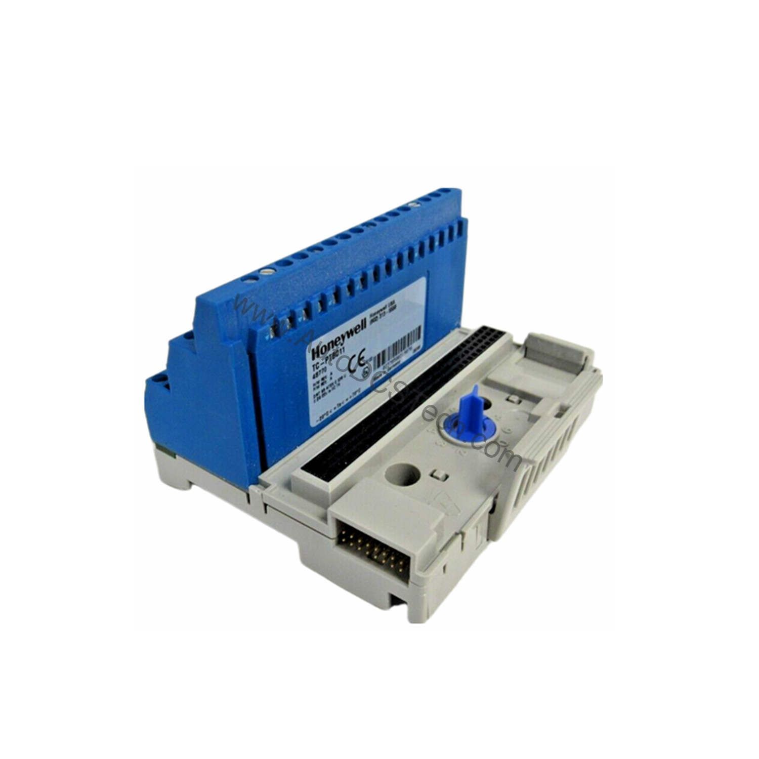
Engineers working in process industries often face a common dilemma: how to safely terminate intrinsically safe field wiring while maintaining a clean, serviceable connection point for the I/O module. The Honeywell TC-PTBC11 terminal base solves this by providing a dedicated, mechanically keyed mounting point with 52 screw terminals, arranged in one row of 16 and two rows of 18. This configuration allows for orderly wiring of power, I/O signals, and backplane communications without guesswork.
Intrinsically Safe Wiring in Process Automation
The TC-PTBC11 is designed for use with intrinsically safe I/O modules in hazardous areas. Its input power channel accepts Ui 10Vdc and Ii 2.5A, ensuring safe energy levels. The backplane bus uses a vendor-specific 16-pole plug and socket, limiting voltage and current to safe values.
Compatibility and Integration
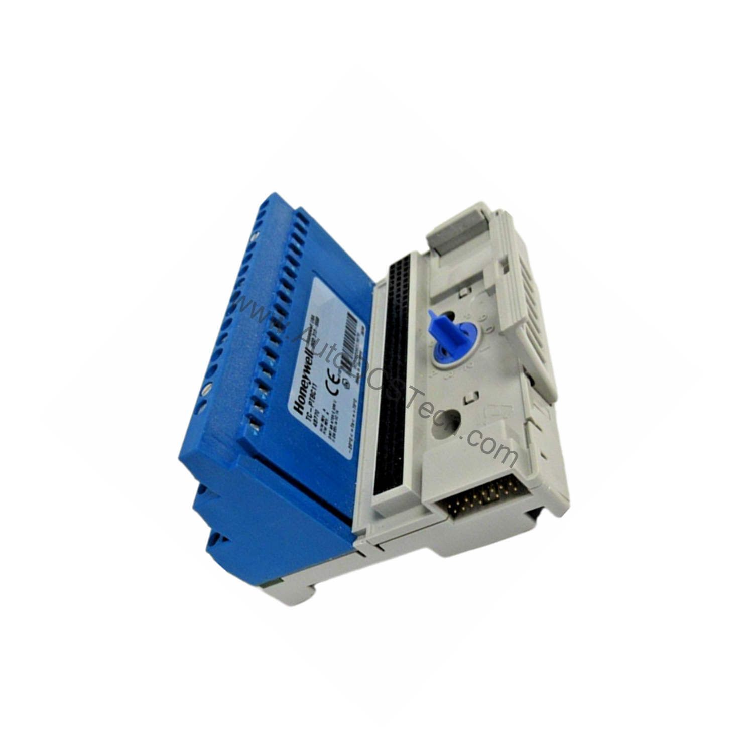
The TC-PTBC11 is part of the Honeywell series of terminal bases and is compatible with Honeywell I/O modules that match the mechanical keying. The vendor-specific backplane bus ensures reliable communication with the control system. For detailed I/O assignments, refer to the specific I/O module documentation.
Purchasing Advice
When ordering the Honeywell TC-PTBC11, confirm the current lifecycle status and availability with AutoDCSTech. Contact them today to place your order or request a quote.
Availability & Condition at AutoDCSTech
| Part Number | TC-PTBC11 |
|---|---|
| Availability | In Stock |
| Condition | New |
| Warranty | One Year |
| Origin | US |