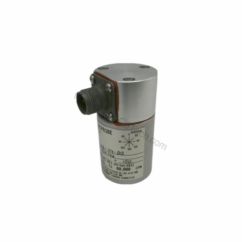
Introduction to the 74712-06-05-04-00
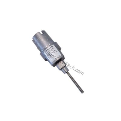
When bearing housing vibration threatens machine reliability, the 74712-06-05-04-00 from Bently Nevada provides a precise measurement solution. This high-temperature two-wire transducer is part of the Seismoprobe family, designed to measure absolute (relative to free space) vibration on bearing housings, casings, or structures. It delivers a voltage output directly proportional to vibration velocity, enabling accurate monitoring in demanding environments.
Engineers choose this model for its rugged moving-coil technology, which offers lower sensitivity to impact or impulsive excitation compared to solid-state velocity transducers. Because it requires no external power, it is convenient for portable measurement applications. The 74712-06-05-04-00 is built to operate in extreme temperatures, making it a reliable choice for high-heat industrial processes.
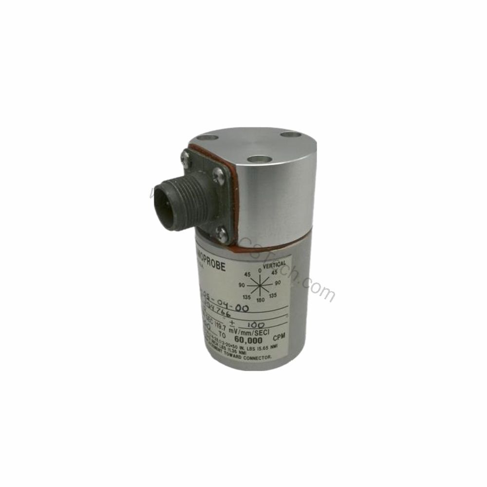
Key Features and Technical Specifications
The 74712-06-05-04-00 offers a range of specifications that ensure dependable performance. Below are the critical parameters extracted from the datasheet:
- Product Type: High-temperature two-wire transducer (series 74712)
- Mounting Angle Option: 0 ±100, 10 Hz (600 cpm) minimum operating frequency
- Mounting Base Option: No base; 1/2-in 20 UNF-3A stud
- Connector Option: Side mount
- Agency Approval: CSA (option 01)
- Height: 82 mm (3.2 in) or 102 mm (4 in) typical depending on connector option
- Diameter: 41 mm (1.6 in) typical
- Operating and Storage Temperature: -29°C to +204°C (-20°F to +400°F)
- Sensitivity: 20 mV/mm/s (500 mV/in/s), ±5% when properly terminated and oriented at the angle of calibration
- Calibration Load: 10 kΩ Terminal "A" to "B"
- Sensitivity Temperature Coefficient: 0.2%/°C
- Dynamic Operating Range: 2.54 mm (0.100 in) peak to peak maximum displacement
- Velocity Range: 25 mm/s (1 in/s) at +22°C of casing vibration at 100 Hz with a 10 kΩ load
- Coil Resistance: 1.25 kΩ ±5%
- Locked Coil Inductance: 125 mH, typical
- Amplitude Linearity: ±5% from 0.01 to 5.0 in/s (0.254 to 127 mm/s) at 100 Hz (6000 CPM)
- Shock Resistance: Withstands 50 g peak maximum acceleration along non-sensitive axis
- Transverse Sensitivity: ±10% maximum of the sensitive axis sensitivity at 100 Hz and 1.0 in/s (2.54 cm/s)
- Polarity of Output Signal: Pin A goes positive with respect to Pin B when the transducer case velocity is towards the connector
- Lead Wire Length: 305 meters (1,000 feet) maximum between Seismoprobe Velocity Transducer and 3300 or Bently Nevada™ 3500 Monitor
- Relative Humidity: To 95%, noncondensing; 100%, non-submerged, when ordered with integral cable
- Maximum Use Altitude: 2000 m (6,561 ft) above sea level
- Mounting Torque: 5.6 N•m (50 in•lb) for 1/2-20, 1/4-20, 1/4-28, 5/8-18, or M10X1 mounting base options; 1.41 N•m (12.5 in•lb) for 8-32 threaded studs
These specifications highlight the transducer's capability to operate in extreme conditions while maintaining measurement accuracy. The high-temperature rating of +204°C makes it suitable for applications where other sensors would fail.
Applications and Use Cases
Its high-temperature tolerance allows installation in locations near hot surfaces, such as steam turbines or gas compressors, where ambient temperatures exceed standard limits. The two-wire design simplifies wiring, reducing installation complexity and potential failure points.
Because it is a moving-coil transducer, it is less sensitive to impulsive forces, making it a good choice for applications with occasional shock loads. Furthermore, its ability to operate without external power enhances portability, enabling temporary measurements during maintenance or diagnostic surveys. For permanent installations, the transducer connects to Bently Nevada monitors (3300 or 3500) with lead wire lengths up to 305 meters, allowing flexible placement.
Installation and Setup
Proper installation is crucial for accurate vibration measurement. The transducer mounts using a 1/2-in 20 UNF-3A stud, with a recommended mounting torque of 5.6 N•m (50 in•lb) for most base options. For 8-32 threaded studs, use 1.41 N•m (12.5 in•lb). Ensure the mounting surface is clean and flat to avoid introducing measurement errors.
Orientation matters: the transducer is calibrated at a specific angle (0 ±100). Position it so that the sensitive axis aligns with the direction of vibration you intend to measure. The side-mount connector option (option 04) allows routing of the cable away from the measurement point, which can be advantageous in tight spaces. When connecting to a monitor, use the specified calibration load of 10 kΩ across terminals A and B to ensure correct sensitivity.
For installations exceeding standard cable lengths, consult the manual for frequency roll-off considerations. The maximum lead wire length is 305 meters, but longer runs may require signal conditioning adjustments.
Maintenance and Reliability
Regular inspection of the transducer and its mounting is essential to maintain reliable operation. Check for any signs of physical damage, corrosion, or loosening of the mounting stud. Verify that the cable is securely connected and not subject to excessive strain or abrasion. Environmental factors such as humidity and temperature should be monitored to ensure they remain within the specified limits.
Because the transducer has no moving parts except the internal coil, it requires minimal maintenance. However, periodic verification of its output against a known vibration source can confirm that sensitivity remains within ±5% of the nominal value. If the transducer is exposed to shock loads beyond its 50 g rating, re-calibration may be necessary.
Following these practices helps extend the service life of the 74712-06-05-04-00 and ensures accurate vibration data for predictive maintenance programs.
Compatibility and Integration
The 74712-06-05-04-00 is designed to work with Bently Nevada monitoring systems, specifically the 3300 and 3500 series. It provides a voltage output that these monitors can process to display vibration levels and trigger alarms. The two-wire configuration simplifies integration, requiring only two connections (A and B) for both power and signal.
For hazardous area installations, the transducer carries approvals including cNRTLus, Class I, Division 1, Groups A, B, C and D T6; Class II, Division 1, Groups E, F and G; Class III; Ex ia IIC T6 Ga; and Ex ec IIC T6 Gc. These certifications ensure safe operation in explosive atmospheres when installed per the applicable codes.
When integrating with a monitor, ensure that the input impedance matches the calibration load (10 kΩ) to achieve the specified sensitivity. Refer to the monitor's manual for proper configuration of measurement channels.
Product Support and Availability
The 74712-06-05-04-00 is available through AutoDCSTech. Our team can provide technical documentation and application support to help you integrate this transducer into your monitoring system.
Availability & Condition at AutoDCSTech
| Part Number | 74712-06-05-04-00 |
|---|---|
| Availability | In Stock |
| Condition | New |
| Warranty | One Year |
| Origin | US |