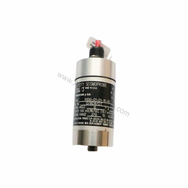
Introduction to the 9200-06-05-05-00
In the evolving landscape of industrial automation, precise vibration monitoring has become a cornerstone of predictive maintenance. The 9200-06-05-05-00 from Bently Nevada addresses this need with a robust two-wire velocity seismoprobe transducer. Designed for continuous operation in demanding environments, this transducer converts mechanical vibration into an electrical signal, enabling early detection of machinery faults.
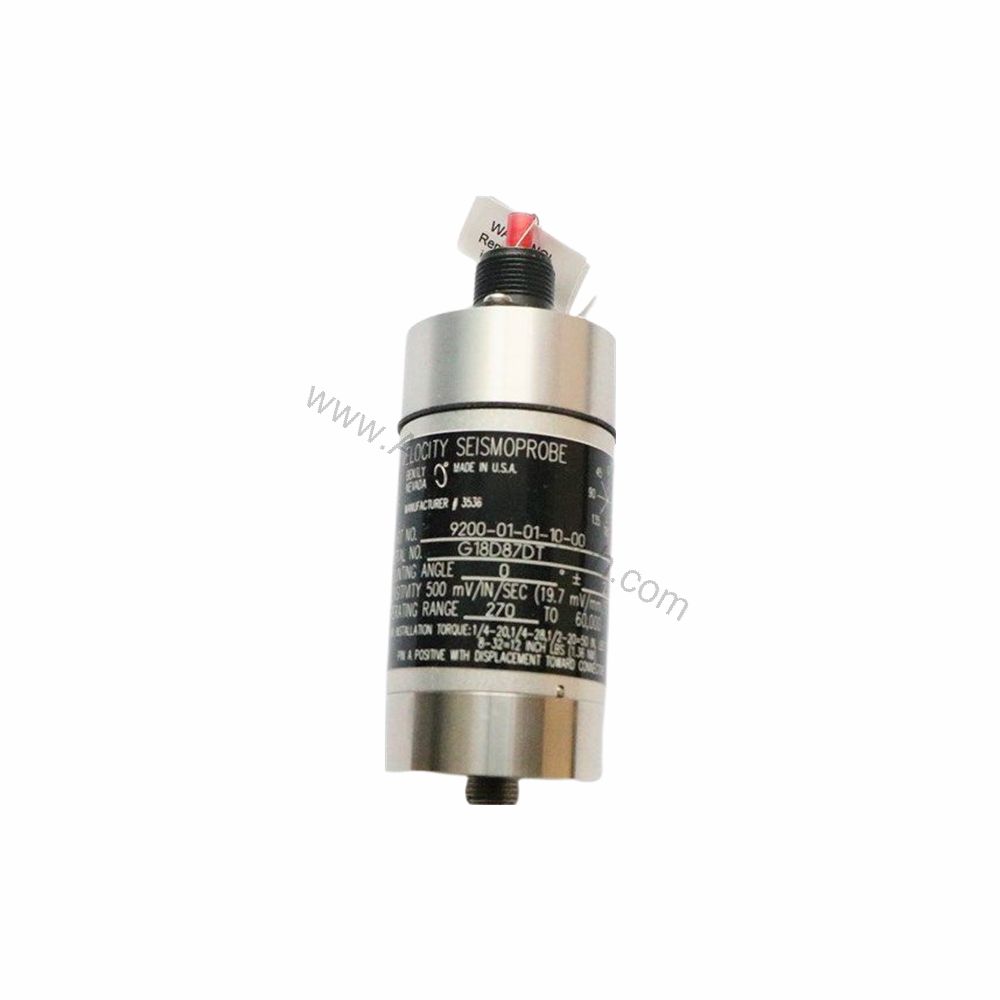
Key Features and Technical Specifications
The 9200-06-05-05-00 offers a set of specifications that ensure accurate and reliable performance. Below are the core parameters derived directly from the product data:
- Sensitivity: 20 mV/mm/s (500 mV/in/s), ±5% when properly terminated and oriented at the angle of calibration.
- Dynamic Operating Range: 2.54 mm (0.100 in) peak-to-peak maximum displacement.
- Velocity Range: 25 mm/s (1 in/s) at +22 °C casing vibration at 100 Hz with a 10 kΩ load.
- Coil Resistance: 1.25 kΩ ±5%.
- Locked Coil Inductance: 125 mH, typical.
- Operating and Storage Temperature: -29°C to +121°C (-20°F to +250°F) for the 9200 model.
- Relative Humidity: Up to 95%, noncondensing; 100% non-submerged when ordered with integral cable.
- Case and Adapter Material: Anodized aluminum A204.
- Gasket Material: Neoprene.
- Height: 102 mm (4 in) typical (depending on connector option).
- Diameter: 41 mm (1.6 in) typical.
- Weight: 300 grams (10.5 ounces) typical.
One distinctive spec is the 20 mV/mm/s sensitivity, which provides a strong signal output for precise vibration analysis. This high sensitivity allows the transducer to detect subtle changes in machinery condition, enabling early intervention and preventing catastrophic failures.
Applications and Use Cases
The 9200-06-05-05-00 is well-suited for vibration monitoring on rotating equipment such as pumps, motors, fans, and compressors. By integrating this transducer into a condition monitoring system, engineers can continuously track machinery health, schedule maintenance proactively, and avoid costly unplanned outages. For example, in a chemical plant, the transducer can be mounted on a critical pump to detect bearing wear early, thereby preventing a complete breakdown.
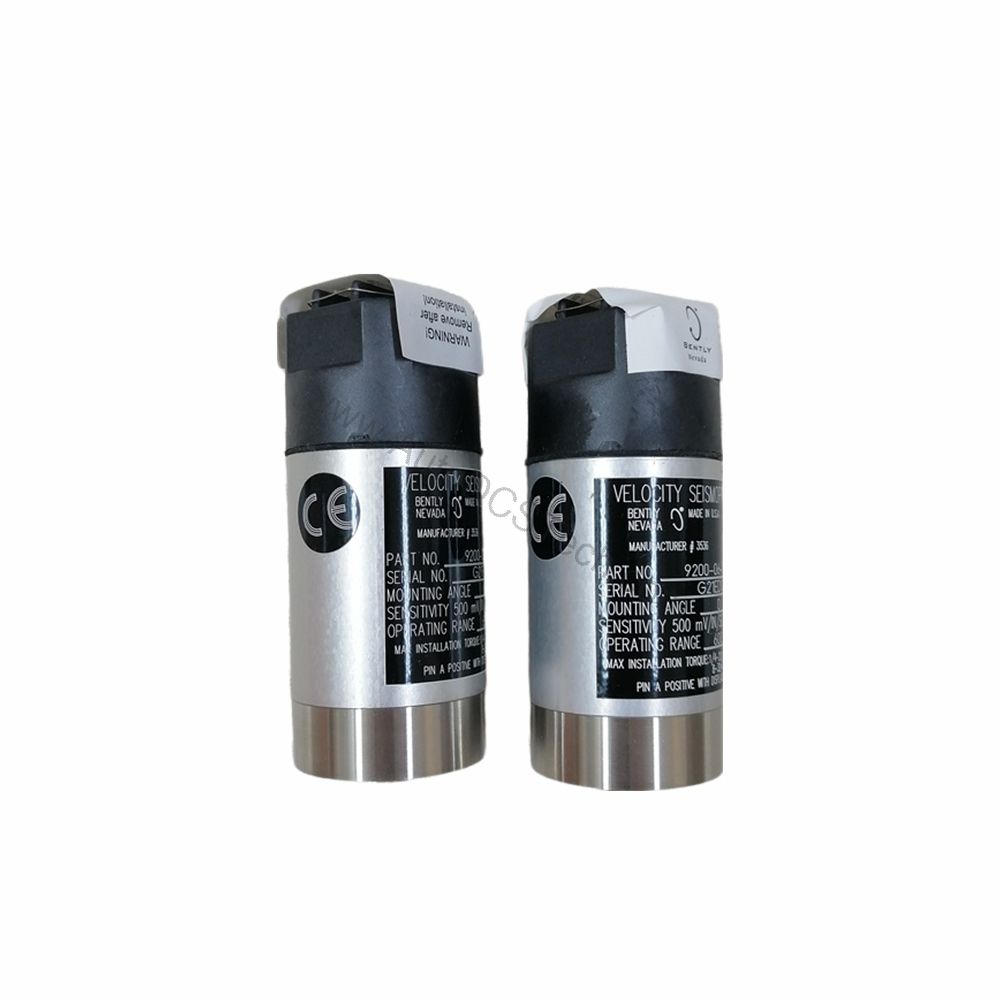
Installation and Setup
Proper installation is crucial for accurate vibration measurement. The 9200-06-05-05-00 features a 1/2-in 20 UNF-3A stud mounting base, which ensures a secure and rigid attachment to the machine surface. The terminal block top-mount connector simplifies wiring, allowing for quick and reliable connections. When installing, ensure the transducer is oriented at the angle of calibration to achieve the specified sensitivity. Also, terminate the output with a 10 kΩ load across terminals A and B for optimal performance. Always follow the manufacturer's guidelines for mounting torque and cable routing to avoid signal degradation.
Maintenance and Reliability
Regular inspection of the transducer and its mounting is recommended to maintain reliable operation. Check for any signs of physical damage, corrosion, or loose connections. The anodized aluminum case and neoprene gasket provide resistance to dust and moisture, but periodic cleaning with a dry cloth can help preserve the seal. Since the transducer has no moving parts, it requires minimal maintenance, contributing to long service life and reduced total cost of ownership. For any issues, consult the Bently Nevada manual or contact AutoDCSTech for support.
Compatibility and Integration
The 9200-06-05-05-00 is a two-wire velocity transducer, meaning it requires only two wires for power and signal transmission. This simplifies integration with most vibration monitoring systems, data acquisition units, and PLCs. The output signal is a voltage proportional to velocity, which can be directly connected to a compatible input module. For detailed integration guidance, refer to the official Bently Nevada documentation or contact AutoDCSTech.
Troubleshooting and Common Issues
If the transducer output is not as expected, first verify the wiring connections and ensure the load resistance is 10 kΩ. Check that the mounting stud is tight and the transducer is correctly oriented. If the signal is noisy, inspect the cable for damage and ensure proper shielding. If the transducer fails to respond, test the coil resistance (1.25 kΩ ±5%) with a multimeter; a reading outside this range indicates a faulty transducer. For persistent issues, contact AutoDCSTech for expert assistance.
Product Support and Availability
The 9200-06-05-05-00 is available from AutoDCSTech, an industrial automation parts supplier. It is supplied as new and original in factory packing, with a 12-month warranty. For inquiries about stock and delivery, contact AutoDCSTech directly. Please verify current lifecycle status and availability with AutoDCSTech before ordering.
Availability & Condition at AutoDCSTech
| Part Number | 9200-06-05-05-00 |
|---|---|
| Availability | In Stock |
| Condition | New |
| Warranty | One Year |
| Origin | US |