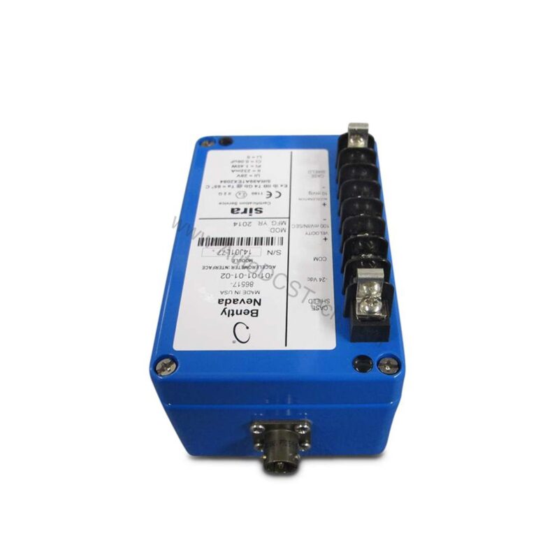
Key Features and Technical Specifications
The 86517-01-01-01-02 offers a set of parameters that matter for accurate vibration analysis. Below are the core specifications extracted from the datasheet:
- Input Sensitivity: 50 pC/g (option 01)
- Filter Corners: 25 Hz high-pass, 350 Hz low-pass
- DC Bias Voltage: -10 Vdc
- Supply Voltage: -23 Vdc to -26 Vdc
- Current Draw: 22 mA maximum
- Acceleration Output: 10 mV/g pk (1.02 mV/m/s² pk), 50 ohm nominal impedance
- Dynamic Range: 750 g without barriers, 500 g with barriers (typical)
- Frequency Response: -3 dB at 4.7 Hz low end; upper -3 dB approximately 5000 Hz with 1000 pF accelerometer and 1000 pF cable
- Velocity Output Accuracy: ±5.0% of calculated velocity at 77°F (25°C)
- Operating Temperature: +32°F to +158°F (0°C to 70°C)
- Storage Temperature: -40°F to +185°F (-40°C to +85°C)
- Humidity: 0 to 95%, noncondensing
One distinctive feature is the overload capacity: 50,000 pC peak for 50 pC/g accelerometers, which protects the module during transient spikes. This ensures reliable operation even in harsh conditions.
Applications and Use Cases
For example, in a turbine train, the 86517-01-01-01-02 conditions accelerometer signals to detect imbalance or bearing wear. Because it supports both 50 pC/g and 100 pC/g accelerometers, you can standardize on one module for different sensor types. Additionally, the high-pass and low-pass filter options allow tailoring to specific vibration frequencies, improving diagnostic accuracy.
Installation and Setup
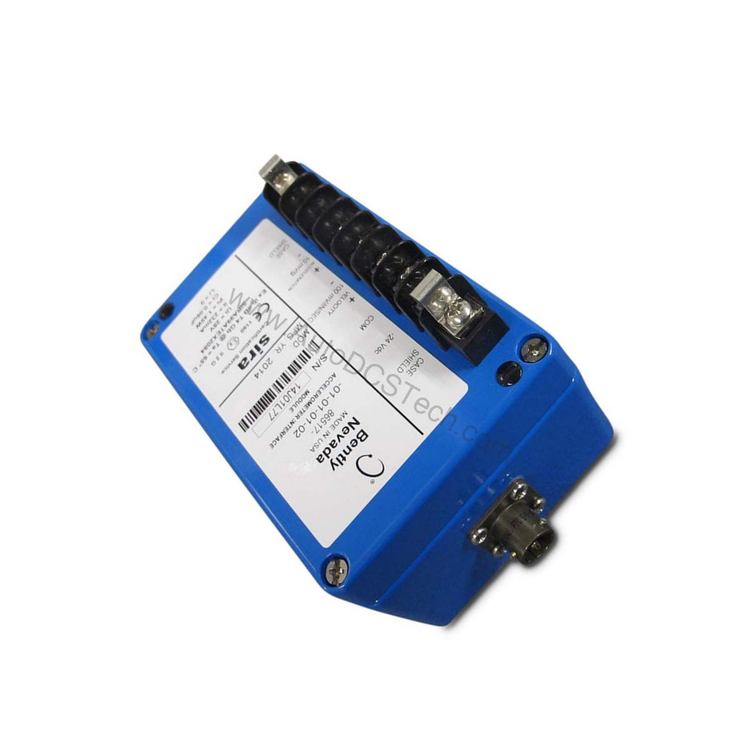
Mounting the module requires two 0.16-inch diameter 8-32 allen head bolts, located at opposite diagonal corners of a 4.45-inch by 2.05-inch rectangle. The module must be isolated from ground to avoid ground loops. The accelerometer input connector is an MS-3112-8-3P, while power and output connections use an 8-lug terminal block. Ensure the accelerometer pole-to-pole capacitance plus extension cable capacitance does not exceed 8300 picofarads, as this affects frequency response.
When wiring, verify that the supply voltage is within -23 Vdc to -26 Vdc and that the current draw stays under 22 mA. For optimal performance, keep cable lengths short and use shielded cables to minimize noise.
Maintenance and Reliability
Regular inspection of the module and its connections helps maintain accuracy. Check the terminal block for tightness and look for signs of corrosion or moisture. The module operates in temperatures from +32°F to +158°F and humidity up to 95% noncondensing, so protect it from condensation. Since the module is not safety-rated, follow standard industrial maintenance practices. Periodic verification of the output signal against a known accelerometer can confirm proper function.
What Is the 86517-01-01-01-02?
When rotating machinery vibration threatens uptime, the 86517-01-01-01-02 from Bently Nevada provides a precise signal conditioning path. This acceleration interface module converts charge output from piezoelectric accelerometers into an usable voltage signal for monitoring systems. Designed for industrial environments, it operates on a supply voltage of -23 Vdc to -26 Vdc and draws a maximum of 22 mA.
As a 159840-01 Acceleration Interface Module, it is built in the U.S.A. and carries CENELEC (SIRA) agency approval. The module accepts differential input from accelerometers with a sensitivity of 50 pC/g pk or 100 pC/g pk, making it versatile for various vibration monitoring setups.
Compatibility and Integration
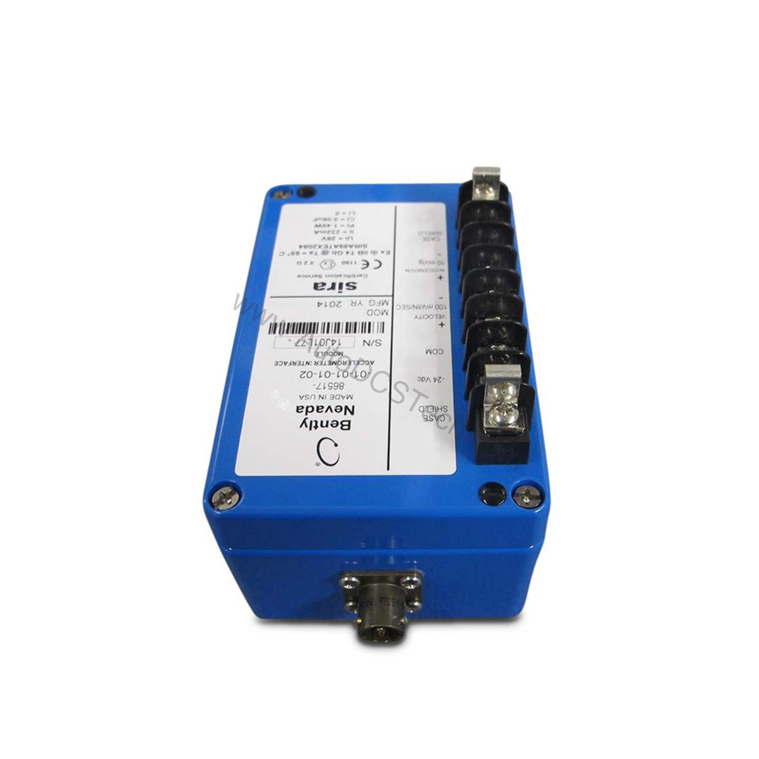
The 86517-01-01-01-02 is designed to work with Bently Nevada monitoring systems. It provides a balanced output with 50 ohm impedance, which can feed into data acquisition or protection systems. The CENELEC (SIRA) approval indicates suitability for certain hazardous area installations, but always check local codes.
Troubleshooting Common Issues
If you see no output, first verify the supply voltage and that the accelerometer is properly connected. A common issue is excessive cable capacitance, which reduces the upper frequency response. If the output is noisy, check grounding and isolation. For acceleration output issues, confirm the accelerometer sensitivity matches the module setting (50 pC/g or 100 pC/g). If velocity output is inaccurate, ensure the filter corners are set correctly for your application.
Product Support and Availability
The 86517-01-01-01-02 is available through AutoDCSTech. Please verify current lifecycle status and availability with AutoDCSTech before ordering. Our team can assist with technical questions and replacement needs.
Availability & Condition at AutoDCSTech
| Part Number | 86517-01-01-01-02 |
|---|---|
| Availability | In Stock |
| Condition | New |
| Warranty | One Year |
| Origin | US |