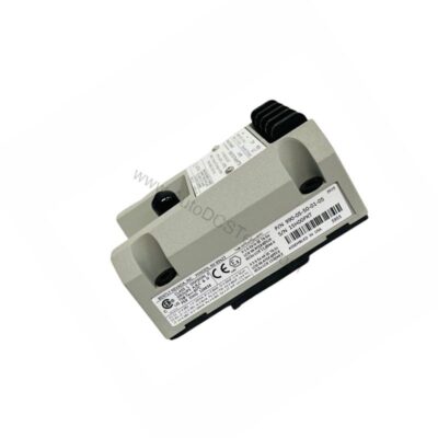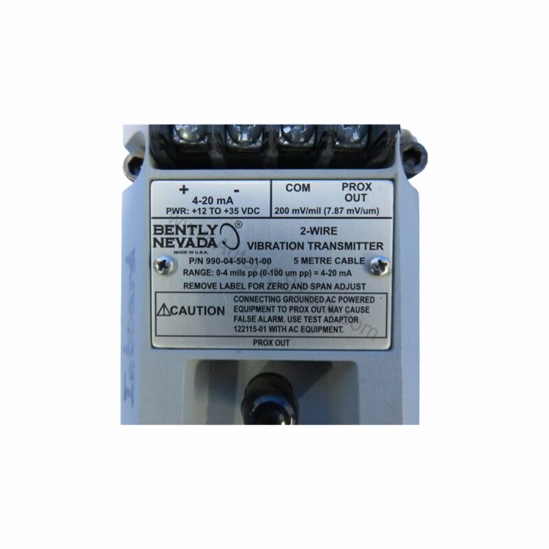
Introduction to the 990-04-50-03-CN Vibration Transmitter
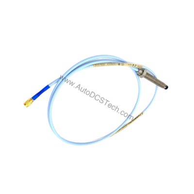
When machine vibration threatens uptime, the 990-04-50-03-CN from Bently Nevada provides a dependable solution. This 990 Vibration Transmitter accepts one non-contacting 3300 NSv Proximity Probe and extension cable, converting shaft vibration into a standard 4-20 mA signal. Designed for continuous operation, it helps maintenance teams detect issues before they escalate.
With a full-scale range of 0-4 mils pp (0-100 μm pp), the 990-04-50-03-CN suits applications requiring precise vibration measurement. Its compact design and DIN clip mounting simplify installation in existing panels.
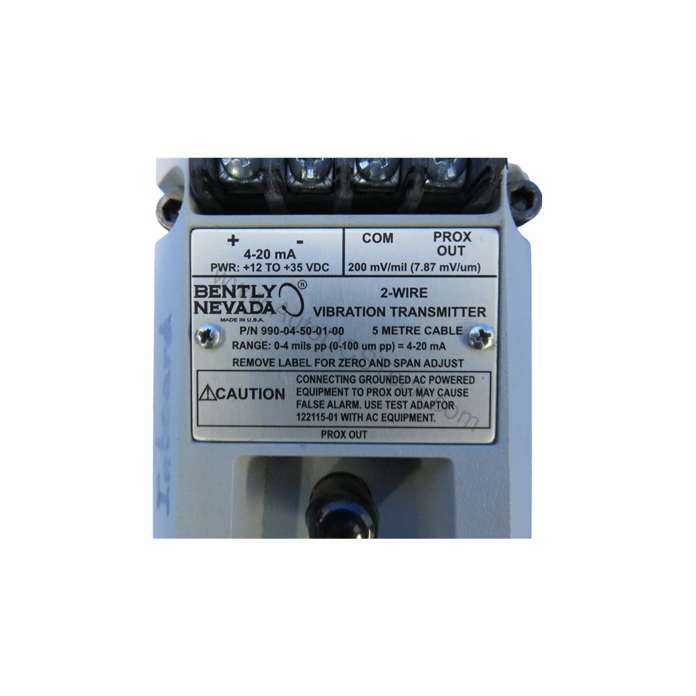
Key Features and Technical Specifications
The 990-04-50-03-CN delivers accurate, repeatable vibration data. Below are the essential specifications from the manufacturer:
- Input: Accepts 1 non-contacting 3300 NSv Proximity Probe and extension cable.
- Power: Requires +12 to +35 Vdc input at the transmitter terminal.
- Output: 4 to 20 mAdc over specified full-scale range in 2-wire configuration.
- Accuracy: Within ±1.5% over specified full-scale range (rated from TEST signal input to voltage across 250 Ω loop resistance).
- Maximum Loop Resistance: 1,000 Ω including cable at 35 Vdc.
- Current Limiting: 23 mA typical.
- Frequency Response: 5 Hz to 6,000 Hz +0, 3 dB.
- Minimum Target Size: 9.5 mm (0.375 in) diameter.
- Probe Gap: Must be gapped between 0.5 and 1.75 mm (20 and 55 mils) from target.
- Not OK/Signal Defeat: Output goes to less than 3.6 mA within 100 µs after a Not OK condition; restores within 2-3 seconds after removal.
These specs ensure reliable performance in demanding industrial environments. The 23 mA current limiting protects the loop, while the fast Not OK response alerts operators to faults.
Applications and Use Cases
Maintenance engineers rely on the 990-04-50-03-CN for continuous vibration monitoring of rotating machinery such as pumps, fans, and motors. Its 4-20 mA output integrates directly with PLCs, DCS, and SCADA systems, enabling real-time trend analysis.
Because the transmitter accepts a 3300 NSv probe, it suits retrofits in existing Bently Nevada monitoring installations. The DIN clip mounting option (Option 03) allows quick panel mounting, reducing installation time.
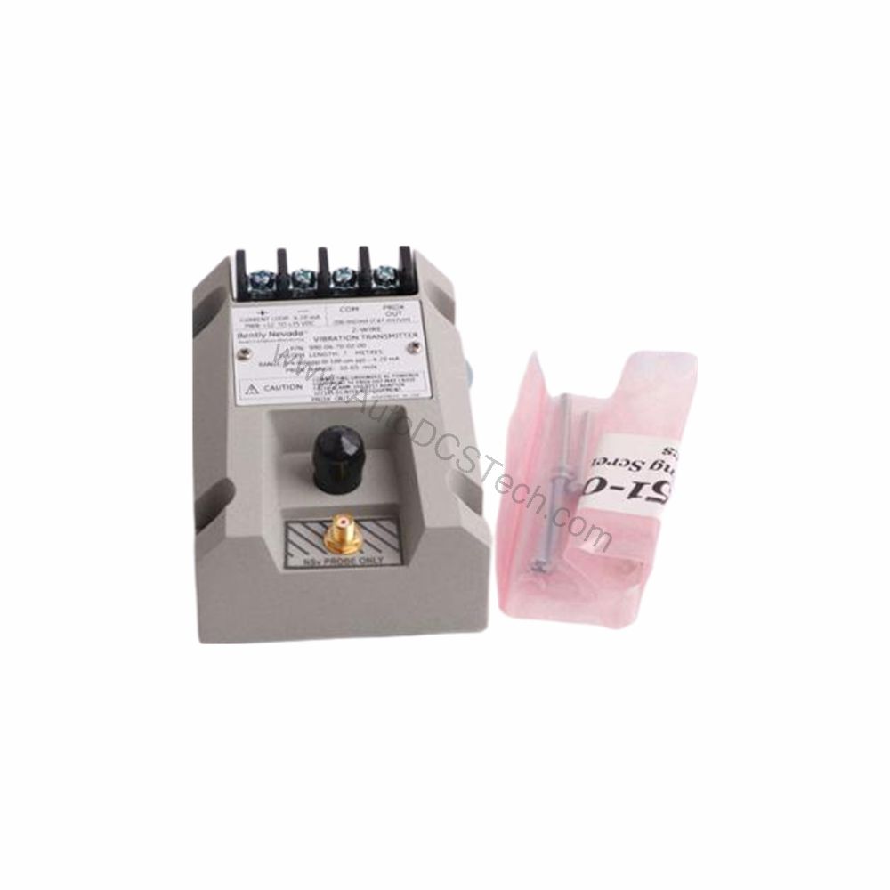
Installation and Setup Guidance
Proper installation is critical for accurate readings. First, mount the transmitter using the included DIN clips and screws. Ensure the proximity probe is gapped between 0.5 and 1.75 mm from the target shaft. Then, connect the probe and extension cable to the transmitter input.
Power the transmitter with +12 to +35 Vdc at the terminal. The 2-wire configuration simplifies wiring: the loop current carries both power and signal. Verify that total loop resistance (including cable) does not exceed 1,000 Ω at 35 Vdc.
After installation, perform a zero and span adjustment using the non-interacting external adjustments. Confirm the output corresponds to the full-scale range (0-4 mils pp).
Maintenance and Reliability
Regular inspection ensures long-term reliability. Check the probe gap periodically, as thermal expansion or shaft movement can alter it. Verify the loop power supply stays within +12 to +35 Vdc. Clean the transmitter enclosure with a dry cloth; avoid solvents that could damage the unit.
The 990-04-50-03-CN is designed for minimal maintenance. Its solid-state electronics have no moving parts, reducing wear. The Not OK self-check feature alerts you to internal faults, allowing proactive replacement.
Compatibility and Integration
This transmitter works with the 3300 NSv proximity probe and extension cable. The 4-20 mA output is universally accepted by most control systems. For hazardous area locations, the transmitter supports NonHazardous, Zone 2, or Div 2 installations with a 28 V power supply (as per data).
Because it uses standard 2-wire loop power, integration with existing analog input modules is straightforward. No special communication protocols are required.
Troubleshooting Common Issues
If the output is stuck at less than 3.6 mA, a Not OK condition may exist. Check probe gap and cable connections. If the output is saturated, verify the target is within the minimum size (9.5 mm diameter) and that the gap is correct.
For loop resistance issues, measure the total resistance; if it exceeds 1,000 Ω, reduce cable length or use a higher supply voltage (up to 35 Vdc). If accuracy drifts, recalibrate zero and span.
Availability and Support
The 990-04-50-03-CN is available from AutoDCSTech. Contact us for current stock and lead times. Our team can assist with technical questions and ordering.
Please verify lifecycle status with AutoDCSTech before ordering.