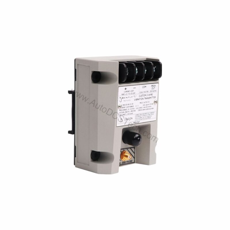
Why Choose the 990-04-70-03-CN for Vibration Monitoring?
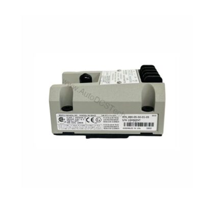
When machinery vibration threatens uptime, how do you ensure accurate, real-time data without complex setups? The 990-04-70-03-CN from Bently Nevada answers this challenge. This 990 Vibration Transmitter converts proximity probe signals into a standard 4-20 mA loop, simplifying integration with existing control systems. Designed for reliability, it provides continuous monitoring in non-hazardous, Zone 2, or Div 2 locations.
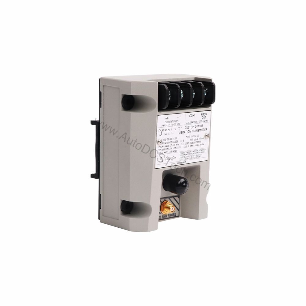
Key Features and Technical Specifications
The 990-04-70-03-CN is engineered for precision and durability. Below are the core specifications that define its performance:
- Input: Accepts one non-contacting 3300 NSv Proximity Probe and extension cable.
- Power: Requires +12 to +35 Vdc input at the transmitter terminal.
- Output: 4 to 20 mAdc over specified full-scale range in 2-wire configuration.
- Full-scale Option: 04 – 0-4 mils pp (0-100 μm pp).
- System Length Option: 70 – 7.0 meters (23.0 feet).
- Mounting Option: 03 – DIN clips and screws.
- Agency Approval: CN – Approvals country specific.
- Maximum Loop Resistance: 1,000 Ω including cable at 35 Vdc.
- Current Limiting: 23 mA typical.
- Frequency Response: 5 Hz to 6,000 Hz +0, 3 dB.
- Minimum Target Size: 9.5 mm (0.375 in) diameter.
- Probe Gap: Must be gapped between 0.5 and 1.75 mm (20 and 55 mils) from target.
- NOT OK/Signal Defeat: Output goes to less than 3.6 mA within 100 µs after a Not OK condition; restored within 2-3 seconds after removal.
- Weight: 0.43 kg (0.9 lbm).
Performance and Accuracy
Accuracy matters in vibration monitoring. The 990-04-70-03-CN delivers 4-20 mA loop accuracy within ±1.5% over the specified full-scale range, measured from the TEST signal input to the voltage across a 250 Ω loop resistance. This error is in addition to the Prox Out Incremental Scale Factor, ensuring you get reliable data for critical decisions.
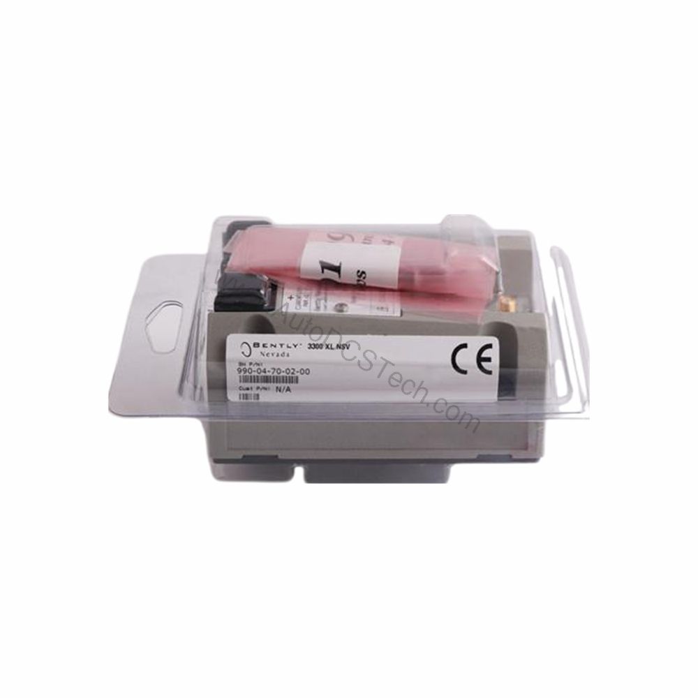
Installation and Setup
Proper installation ensures optimal performance. The transmitter mounts using DIN clips and screws (Mounting Option 03). The system length is 7.0 meters (23.0 feet), which includes the extension cable. For non-hazardous, Zone 2, or Div 2 hazardous area locations, a 28 V power supply is recommended. Ensure the probe gap is set between 0.5 and 1.75 mm (20 and 55 mils) from the target to achieve full-scale range.
Maintenance and Reliability
Routine inspection is key to long-term reliability. Periodically verify the transmitter's output and loop resistance. The current limiting feature (23 mA typical) protects the loop from overcurrent conditions. The NOT OK/signal defeat function quickly signals faults, allowing prompt corrective action. Follow the manufacturer's manual for detailed maintenance procedures.
Compatibility and Integration
The 990-04-70-03-CN integrates seamlessly with systems that accept 4-20 mA signals. Its 2-wire configuration simplifies wiring, and the maximum loop resistance of 1,000 Ω ensures compatibility with most control systems. The transmitter accepts a 3300 NSv Proximity Probe, making it a direct replacement for existing setups.
Troubleshooting Common Issues
If the output signal drops below 3.6 mA, a Not OK condition is indicated. This could be due to probe gap issues, cable faults, or power supply problems. Check the probe gap and ensure it is within the specified range. Verify the power supply voltage is between +12 and +35 Vdc. If the issue persists, consult the official Bently Nevada documentation or contact AutoDCSTech for support.
Product Support and Availability
The 990-04-70-03-CN is available from AutoDCSTech. In stock and ready to ship. Contact AutoDCSTech for current availability and lifecycle status before ordering.