Introduction to the 991-06-50-01-01
When axial thrust position monitoring demands reliable, continuous data, the 991-06-50-01-01 from Bently Nevada provides a robust solution. This probe vibration transmitter converts proximity probe signals into a standard 4-20 mA output, enabling seamless integration with PLCs, DCS, and SCADA systems. Engineered for industrial environments, it offers precise measurement over a full-scale range of 0.6-0-0.6 mm, making it suitable for critical rotating machinery protection.
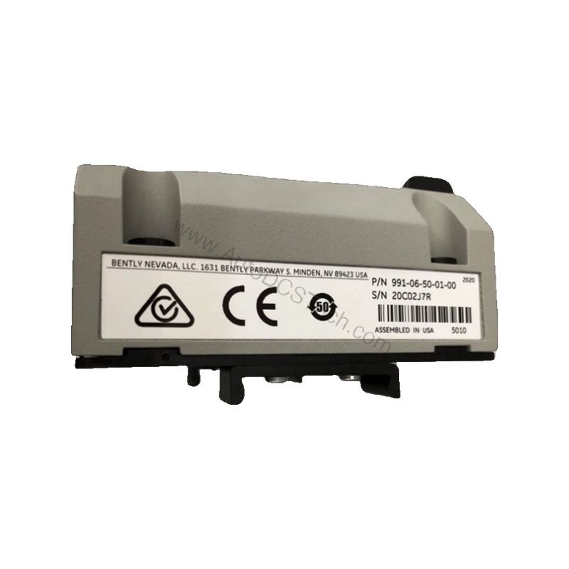
Key Features and Technical Specifications
The 991-06-50-01-01 is designed with performance and reliability in mind. Below are the core specifications:
- Output Signal: 4-20 mA DC in a 2-wire configuration.
- Power Requirement: +12 to +35 Vdc input at the transmitter terminal.
- Linear Range: 0.25 to 1.65 mm for proximity output, suitable for 0.6-0-0.6 mm or 25-0-25 mils current loop linear ranges.
- Loop Accuracy: Within ±1.5% over full scale (typical), rated from test signal input to voltage across a 250 Ω loop resistance.
- Maximum Loop Resistance: 1,000 Ω including cable at 35 Vdc.
- Current Limiting: 23 mA typical.
- Zero and Span: Non-interacting external adjustments.
- Not OK/Signal Defeat: Output goes to less than 3.6 mA within 100 µs after a Not OK condition; restored within 0.1 seconds after removal.
These specifications ensure accurate and responsive thrust monitoring, critical for preventing machinery damage.
Applications and Use Cases
The 991-06-50-01-01 is primarily used for axial thrust measurement in turbomachinery, compressors, and large rotating equipment. Its 4-20 mA output allows direct interface with control systems, enabling continuous monitoring and alarm annunciation. For example, in a steam turbine, the transmitter provides real-time thrust position data, allowing operators to detect abnormal axial movement before it leads to catastrophic failure. This proactive approach reduces downtime and maintenance costs.
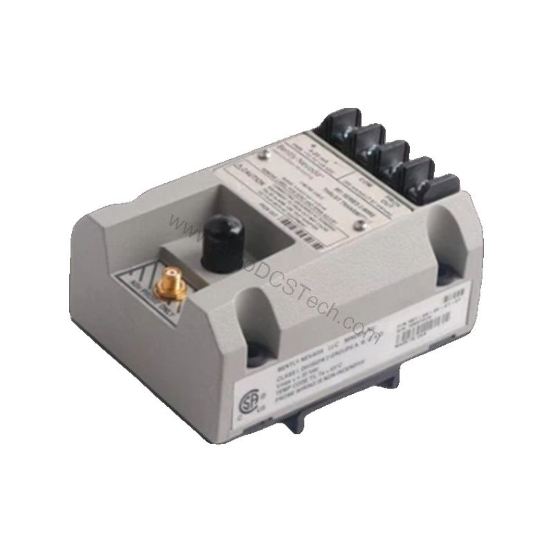
Installation and Mounting
Mounting the 991-06-50-01-01 is straightforward with its 35 mm DIN-rail clips, simplifying panel integration. The system length option of 5.0 meters (16.4 feet) provides flexibility in probe placement. Ensure the transmitter is installed in a location that meets the operating temperature range of -35°C to +85°C (-31°F to +185°F) and storage range of -51°C to +100°C (-60°F to +212°F). Proper wiring of the 2-wire loop is essential for accurate signal transmission.
Maintenance and Reliability
Routine inspection of the 991-06-50-01-01 is recommended to verify its operation. Check the integrity of the probe and cable connections periodically. The transmitter's design includes a Not OK/Signal Defeat feature that forces the output below 3.6 mA within 100 µs of a fault, ensuring fail-safe operation. This self-diagnostic capability enhances system reliability and simplifies troubleshooting.
Compatibility and Integration
The 4-20 mA output of the 991-06-50-01-01 is universally compatible with most industrial control systems, including PLCs, DCS, and SCADA. It accepts one non-contacting 3300 NSv proximity probe and extension cable, making it a drop-in solution for existing Bently Nevada monitoring systems. The transmitter's linear range is optimized for 0.6-0-0.6 mm or 25-0-25 mils current loop ranges, ensuring accurate scaling.
Troubleshooting and Common Issues
If the output signal is not within the expected range, first verify the power supply is within +12 to +35 Vdc. Check loop resistance; it must not exceed 1,000 Ω at 35 Vdc. If the output goes below 3.6 mA, the Not OK condition may be active—inspect the probe and cable for damage. The non-interacting zero and span adjustments allow for easy recalibration without affecting each other.
Support and Availability
The 991-06-50-01-01 is available through AutoDCSTech, your trusted industrial automation parts supplier. For lifecycle status and availability, please contact AutoDCSTech before ordering. Our team can assist with technical questions and ensure you receive the right part for your application.