Introduction to the 991-06-50-03-01 Probe Vibration Transmitter
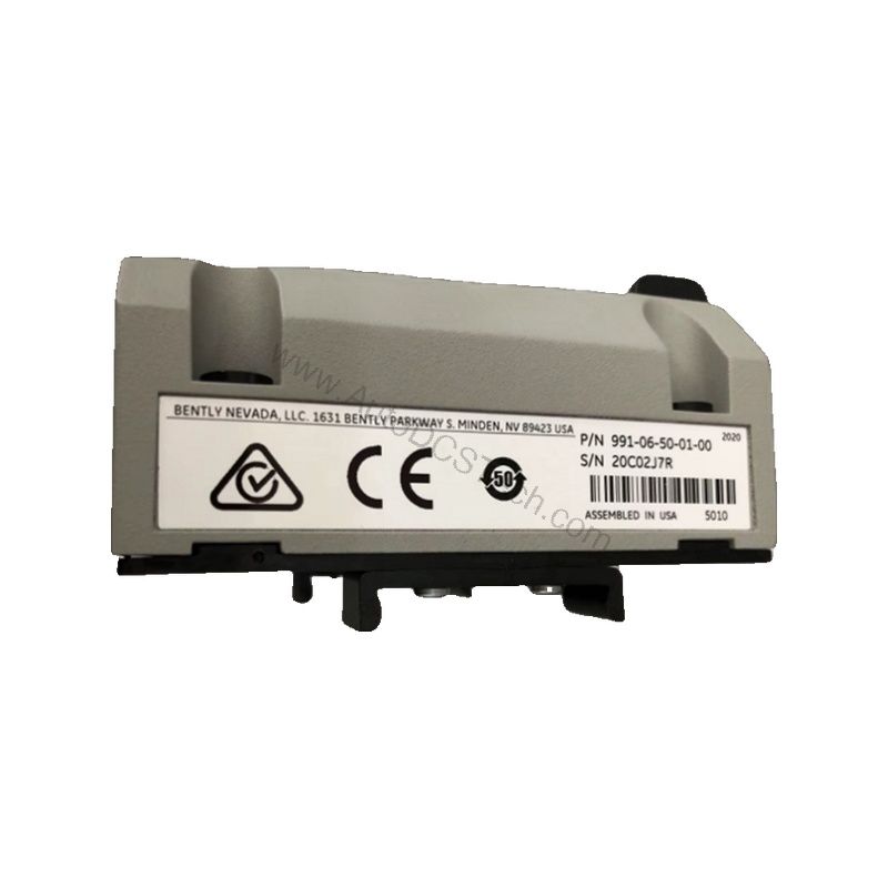
When axial thrust monitoring is critical for turbomachinery reliability, the 991-06-50-03-01 from Bently Nevada provides a proven solution. This probe vibration transmitter converts proximity probe signals into a standard 4-20 mA loop, enabling seamless integration with existing control and monitoring systems. Designed for DIN rail mounting, it simplifies installation in industrial cabinets.
Key Features and Technical Specifications
The 991-06-50-03-01 is engineered for precision and durability. Its core specifications include:
- Input: Accepts one non-contacting 3300 NSv proximity probe and extension cable.
- Power: Requires +12 to +35 Vdc input at the transmitter terminal.
- Output: 4-20 mAdc over the specified full-scale range in a 2-wire configuration.
- Accuracy: Within ±1.5% over the full-scale range (typical), measured from test signal to voltage across a 250 Ω loop resistance.
- Maximum Loop Resistance: 1,000 Ω including cable at 35 Vdc.
- Current Limiting: 23 mA typical.
- Linear Range: 0.25 to 1.65 mm for Prox Out, suitable for 0.6-0-0.6 mm or 25-0-25 mils current loop linear ranges.
- Environmental: Operating temperature -35°C to +85°C; storage -51°C to +100°C.
- Weight: 0.43 kg (0.9 lbm).
The transmitter's non-interacting external zero and span adjustments allow for precise calibration without cross-talk, simplifying setup and maintenance.
Applications and Use Cases
Primarily used for axial thrust monitoring in rotating machinery, the 991-06-50-03-01 is suitable for compressors, turbines, and pumps. Its 4-20 mA output integrates directly with PLCs, DCS, and SCADA systems, enabling continuous vibration and thrust monitoring. The DIN rail mount and CSA Division 2 approval make it appropriate for hazardous industrial environments.
Installation and Setup
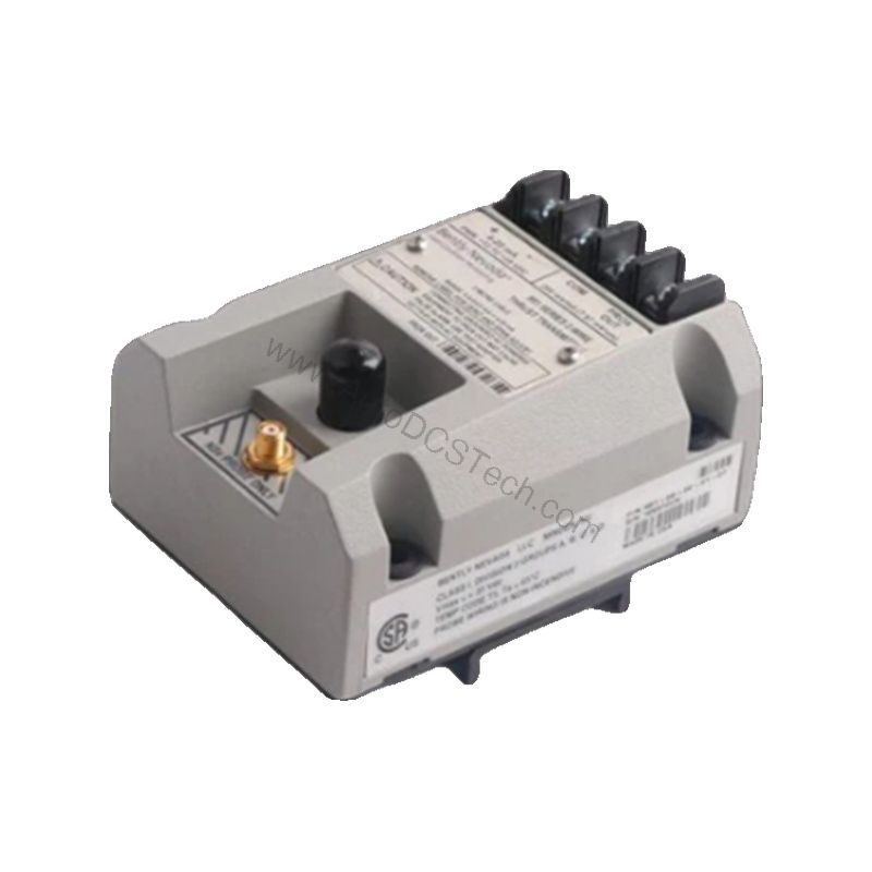
Mounting the 991-06-50-03-01 is straightforward with DIN clips and screws. The transmitter accepts a 3300 NSv proximity probe and extension cable, and the 5.0-meter (16.4 feet) system length option provides flexibility in probe placement. For optimal performance, ensure the probe is correctly positioned within the linear range (0.25 to 1.65 mm) and that the loop resistance does not exceed 1,000 Ω at 35 Vdc. Always follow the manufacturer's installation manual for detailed wiring and calibration procedures.
Maintenance and Reliability
Regular inspection of the transmitter and probe is recommended to ensure accurate readings. Because the device is safety-related, maintenance should be performed only by qualified personnel following the manufacturer's safety manual. Periodically verify the output signal and check for any signs of environmental stress, such as temperature extremes or vibration. The transmitter's robust design, with an operating temperature range of -35°C to +85°C, ensures reliable performance in demanding conditions.
Troubleshooting and Common Issues
If the output signal drops below 3.6 mA, the transmitter is indicating a Not OK condition. This can occur due to probe damage, cable faults, or power supply issues. The signal output goes to less than 3.6 mA within 100 µs after a Not OK condition, and restores within 0.1 seconds after the condition is removed. For persistent issues, verify the power supply voltage (+12 to +35 Vdc) and check the loop resistance. If problems persist, consult the official Bently Nevada documentation or contact AutoDCSTech for support.
Support and Availability
The 991-06-50-03-01 is available from AutoDCSTech. Please verify current lifecycle status and availability before ordering. For technical support, contact AutoDCSTech with your specific application requirements.