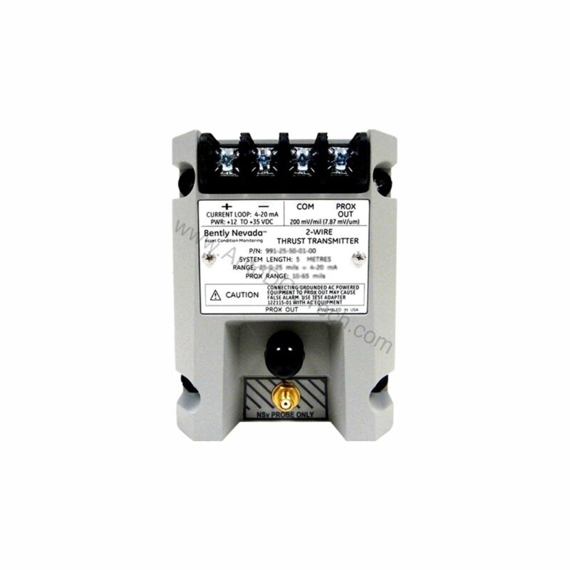
Overview of the Bently Nevada 991-06-70-01-CN Thrust Transmitter
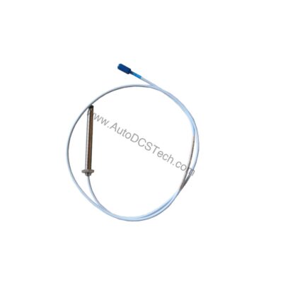
When axial thrust monitoring is critical to your rotating machinery's reliability, the 991-06-70-01-CN from Bently Nevada provides a precise, loop-powered solution. This probe vibration transmitter converts the signal from a non-contacting 3300 NSv proximity probe into a standard 4-20 mA output, making it easy to integrate with your existing control systems.
Designed for axial (thrust) position measurements, this unit is factory-configured for a full-scale range of 0.6-0-0.6 mm and includes a 7.0-meter (23.0 feet) system length. The mounting option includes 35 mm DIN-rail clips, simplifying installation in your panel.
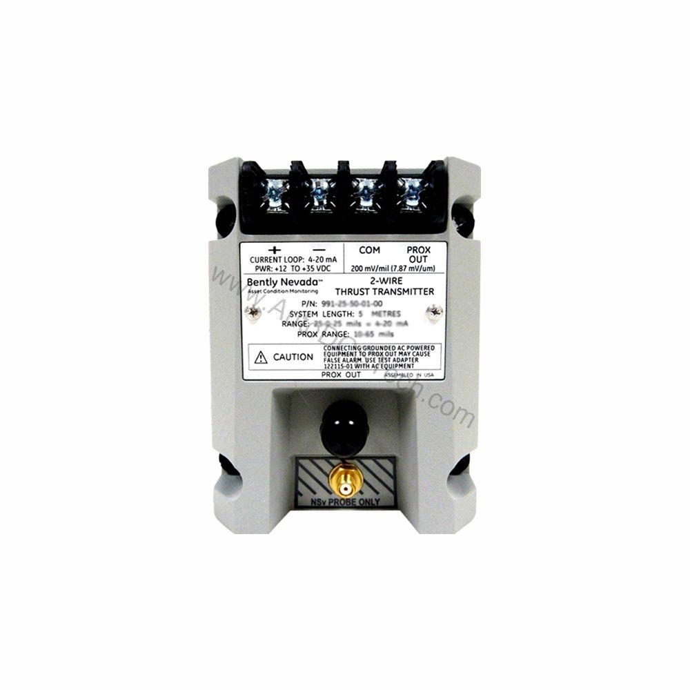
Key Features and Technical Specifications
Let's examine the technical parameters that define the 991-06-70-01-CN's performance. These specifications are critical for ensuring the transmitter meets your application's requirements.
- Power Requirement: The transmitter operates on +12 to +35 Vdc input at the terminal, offering flexibility in power supply selection.
- Output Signal: It provides a 4-20 mA dc output over the specified full-scale range in a 2-wire configuration, ideal for long-distance signal transmission.
- Linear Range: The linear range is 0.25 to 1.65 mm for Prox Out, suitable for 0.6-0-0.6 mm or 25-0-25 mils current loop linear ranges.
- Accuracy: The 4-20 mA loop accuracy is within ±1.5% over the specified full-scale range (typical), measured from the TEST signal input to the voltage across a 250 Ω loop resistance.
- Maximum Loop Resistance: Up to 1,000 Ω including cable at 35 Vdc, ensuring compatibility with most control system input cards.
- Current Limiting: The output is current limited to 23 mA typical, protecting the loop in fault conditions.
- Not OK/Signal Defeat: The signal output drops to less than 3.6 mA within 100 µs after a Not OK condition, and restores within 0.1 seconds after the condition is removed.
- Environmental Limits: Operating temperature range is -35°C to +85°C (-31°F to +185°F); storage temperature is -51°C to +100°C (-60°F to +212°F).
- Weight: The transmitter weighs 0.43 kg (0.9 lbm).
These specifications allow the 991-06-70-01-CN to deliver reliable performance in demanding industrial environments.
Applications and Use Cases
This thrust transmitter is specifically designed for axial position monitoring in turbomachinery, such as steam turbines, compressors, and large pumps. In these applications, excessive axial thrust can lead to catastrophic bearing failure. By providing a continuous 4-20 mA signal proportional to thrust position, the 991-06-70-01-CN enables early detection of abnormal conditions, allowing operators to take corrective action before damage occurs.
For example, in a steam turbine, the transmitter can be connected to a PLC or DCS to trigger an alarm if the thrust bearing wears beyond acceptable limits. Moreover, the 4-20 mA output is universally accepted, simplifying integration with existing monitoring systems.
Installation and Setup Guidance
Proper installation is essential for accurate measurements. The transmitter mounts on a 35 mm DIN rail using the included clips. Ensure that the DIN rail is securely grounded and that the transmitter is positioned away from excessive vibration or heat sources.
When wiring, connect the loop power supply (+12 to +35 Vdc) to the transmitter's positive terminal and the 4-20 mA output to the negative terminal, observing correct polarity. The system length of 7.0 meters (23.0 feet) includes the probe and extension cable, so plan the routing to avoid sharp bends or damage.
After installation, verify the zero and span adjustments. The 991-06-70-01-CN features non-interacting external adjustments, allowing you to calibrate the output without affecting the other parameter. Always refer to the Bently Nevada manual for detailed wiring and calibration procedures.
Maintenance and Reliability
To ensure long-term reliability, periodic inspection of the transmitter and probe is recommended. Check the DIN rail mounting for tightness and inspect cables for wear or damage. The transmitter's operating temperature range of -35°C to +85°C means it can withstand harsh environments, but avoid exposing it to temperatures beyond these limits.
Because the 991-06-70-01-CN is a solid-state device, it requires minimal maintenance. However, we advise verifying the loop accuracy periodically using a calibrated test signal. If the output deviates beyond the ±1.5% specification, recalibrate the zero and span as described in the manual.
Compatibility and Integration
The 4-20 mA output makes the 991-06-70-01-CN compatible with virtually any control system that accepts analog inputs, including PLCs, DCSs, and SCADA systems. It accepts one non-contacting 3300 NSv proximity probe and extension cable, which is a standard in the industry.
This transmitter is a direct replacement for older Bently Nevada models, providing the same functionality with modern reliability. Its 2-wire configuration simplifies wiring, reducing installation costs.
Troubleshooting Common Issues
If the output signal is not within the expected range, first verify the power supply voltage at the transmitter terminal. It must be between +12 and +35 Vdc. Next, check the loop resistance; the maximum is 1,000 Ω at 35 Vdc. If the resistance is too high, the output may be limited.
If the output goes below 3.6 mA, a Not OK condition may be present. This could indicate a probe fault, cable break, or target out of range. The signal will restore within 0.1 seconds after the condition is removed, so transient faults may be self-clearing.
For persistent issues, consult the Bently Nevada documentation or contact AutoDCSTech for technical support.
Product Support and Availability
The Bently Nevada 991-06-70-01-CN is available from AutoDCSTech. We are an industrial automation parts supplier committed to providing genuine components. Contact us for current availability and lifecycle status before ordering.