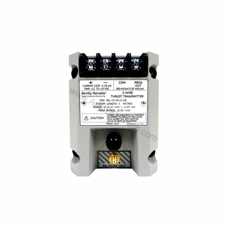
Overview of the Bently Nevada 991-06-70-02-05
When machinery thrust or axial vibration threatens uptime, the 991-06-70-02-05 delivers precise, real-time data. This Bently Nevada probe vibration transmitter converts proximity probe signals into a standard 4-20 mA loop, enabling seamless integration with PLCs, DCS, and SCADA systems. Its compact DIN-rail mount simplifies panel installation, while the 7.0-meter system length offers flexible sensor placement.
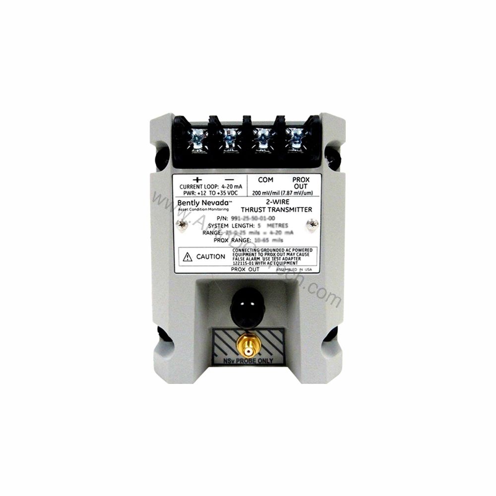
Key Features and Technical Specifications
- Model: 991 Thrust Transmitter
- Full-scale option: 0.6-0-0.6 mm (25-0-25 mils)
- System length: 7.0 meters (23.0 feet)
- Mounting: Bulkhead screws, DIN rail
- Output: 4-20 mA (2-wire)
- Power: +12 to +35 Vdc at transmitter terminal
- Linear range: 0.25 to 1.65 mm for Prox Out
- Accuracy: ±1.5% of full scale (typical)
- Max loop resistance: 1000 Ω at 35 Vdc
- Current limiting: 23 mA typical
One standout feature is the Not OK/Signal Defeat function. If a fault occurs, the output drops below 3.6 mA within 100 µs, immediately alerting control systems. This rapid response helps prevent undetected sensor failures, enhancing overall plant safety.
Comparison with Alternative Transmitters
Compared to standard 4-20 mA transmitters without built-in signal defeat, the 991-06-70-02-05 offers faster fault indication and a wider linear range. Many conventional units require external signal conditioners, whereas this model integrates directly with a 3300 NSv probe. Its DIN-rail mounting also simplifies retrofit projects, reducing installation time versus panel-mount enclosures.
Applications and Use Cases
This transmitter is designed for axial thrust monitoring in rotating machinery such as turbines, compressors, and pumps. In petrochemical plants, it helps detect thrust bearing wear before catastrophic failure. Similarly, power generation facilities use it to monitor turbine shaft position, ensuring safe operation during load changes. Its ATEX and CSA approvals make it suitable for hazardous areas, including Zone 0 and Division 2 environments.
Installation and Setup
Mount the 991-06-70-02-05 on a standard DIN rail using the bulkhead screws provided. Connect the 3300 NSv probe and extension cable to the transmitter input. Wire the 4-20 mA loop to your control system, observing polarity. Power the unit with +12 to +35 Vdc at the transmitter terminal. Adjust zero and span using the non-interacting external potentiometers. Verify loop resistance does not exceed 1000 Ω at 35 Vdc to maintain accuracy.
Maintenance and Reliability
Regularly inspect the probe and cable for physical damage, especially in high-vibration areas. Check that the DIN rail mounting remains secure. Periodically verify the 4-20 mA output against a known reference to confirm calibration. The transmitter's operating temperature range of -35°C to +85°C allows use in harsh environments, but avoid exceeding these limits. Follow the manufacturer's manual for detailed maintenance procedures.
Troubleshooting Common Issues
If the output is stuck at 4 mA, check the probe gap and cable continuity. A reading below 3.6 mA indicates a Not OK condition—verify probe connection and power supply. For erratic readings, inspect the loop resistance and ensure it is within 1000 Ω. If the zero and span drift, recalibrate using the external adjustments. For persistent issues, consult Bently Nevada documentation or contact AutoDCSTech.
Product Support and Availability
AutoDCSTech offers the 991-06-70-02-05 as a stocked item. Contact our team for current availability and lead times. We provide technical support to help you integrate this transmitter into your monitoring system.