Introduction: The Evolution of Thrust Monitoring
In the early days of rotating machinery protection, monitoring axial thrust required complex, rack-mounted systems with separate signal conditioners and power supplies. Today, the Bently Nevada 991-25-70-01-00 represents a significant leap forward—a compact, loop-powered transmitter that integrates directly with a non-contacting proximity probe. This evolution simplifies installation, reduces panel space, and lowers overall system cost while maintaining the precision that critical machinery protection demands.
For engineers responsible for turbomachinery, compressors, and large pumps, the 991-25-70-01-00 offers a direct path to reliable thrust measurement. Its 4-20 mA output integrates seamlessly with existing PLCs, DCSs, and SCADA systems, making it a versatile choice for both new installations and retrofit projects.
Key Features and Technical Specifications
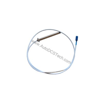
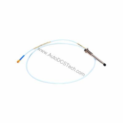
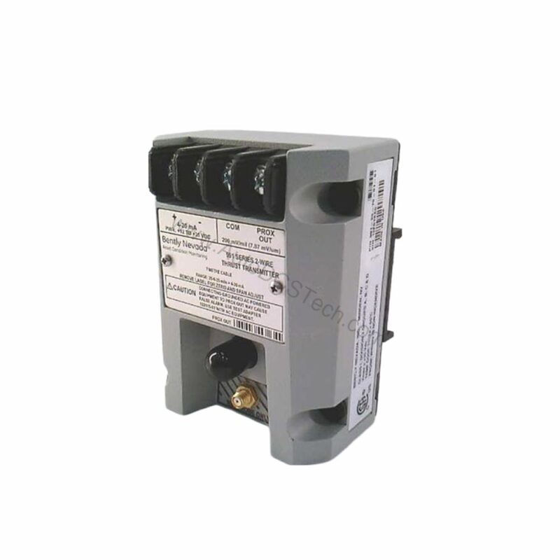
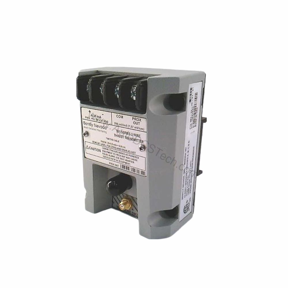
The 991-25-70-01-00 is a thrust transmitter from Bently Nevada's 991 series, designed for axial position monitoring. It accepts input from one non-contacting 3300 NSv proximity probe and extension cable, converting the probe signal into a standard 4-20 mA current loop output.
- Full-scale range: 25-0-25 mils (0.6-0-0.6 mm) linear range.
- System length: 7.0 meters (23.0 feet) probe and extension cable.
- Mounting: 35 mm DIN-rail clips (option 01).
- Output signal: 4-20 mA DC in a two-wire configuration.
- Power requirement: +12 to +35 Vdc input at the transmitter terminal.
- Loop accuracy: Within ±1.5% over the specified full-scale range (typical), measured from the TEST signal input to the voltage across a 250 Ω loop resistance.
- Maximum loop resistance: 1,000 Ω including cable at 35 Vdc.
- Current limiting: 23 mA typical.
- Zero and span: Non-interacting external adjustments.
- Not OK/Signal defeat: Output drops to less than 3.6 mA within 100 µs of a Not OK condition, and restores within 0.1 seconds after removal.
One distinctive feature is the Not OK/Signal Defeat function. This ensures that if the probe or transmitter detects a fault, the output current falls below 3.6 mA, which is outside the normal 4-20 mA range. This provides a clear, unambiguous indication of a problem, enabling rapid troubleshooting and preventing false readings that could lead to incorrect decisions.
Applications and Use Cases
The 991-25-70-01-00 is specifically designed for axial thrust measurement in rotating machinery. Common applications include steam turbines, gas turbines, compressors, and large centrifugal pumps. In these environments, excessive thrust can indicate bearing wear, misalignment, or other mechanical issues that, if left unchecked, can lead to catastrophic failure.
Because the transmitter outputs a standard 4-20 mA signal, it can be connected directly to a PLC analog input module or a DCS. This allows for continuous monitoring, alarm annunciation, and integration with plant control systems. The DIN-rail mounting simplifies installation in existing panels, and the 7.0-meter cable length provides flexibility in probe placement.
Installation and Setup
Mounting the 991-25-70-01-00 is straightforward. The transmitter clips onto a standard 35 mm DIN rail, and the probe connects via the integral cable. The two-wire loop connection requires only two wires for both power and signal, reducing wiring complexity.
Before installation, verify that the power supply provides +12 to +35 Vdc at the transmitter terminal. The loop resistance must not exceed 1,000 Ω at 35 Vdc. For optimal accuracy, calibrate the zero and span using the external adjustments, following the procedures in the Bently Nevada manual.
Maintenance and Reliability
Routine maintenance for the 991-25-70-01-00 is minimal. Periodically inspect the transmitter and probe cable for physical damage, and verify that the DIN-rail clips are secure. The transmitter's operating temperature range is -35°C to +85°C, making it suitable for most industrial environments. Storage temperature range is -51°C to +100°C.
The Not OK/Signal Defeat function enhances reliability by immediately signaling any internal fault. This allows maintenance teams to address issues before they escalate. For safety-critical applications, follow the manufacturer's recommended inspection intervals and always consult the official manual before performing any maintenance.
Troubleshooting Common Issues
If the output current is outside the 4-20 mA range, check for a Not OK condition. The output will drop below 3.6 mA if the probe is not connected properly or if the transmitter detects a fault. Verify the probe gap and that the extension cable is securely attached.
If the output is inaccurate, check the loop resistance and supply voltage. The maximum loop resistance is 1,000 Ω at 35 Vdc; higher resistance may cause errors. Also, confirm that the zero and span adjustments are set correctly.
Product Support and Availability
The Bently Nevada 991-25-70-01-00 is available from AutoDCSTech. Please verify current lifecycle status and availability before ordering. For technical support, contact our team.