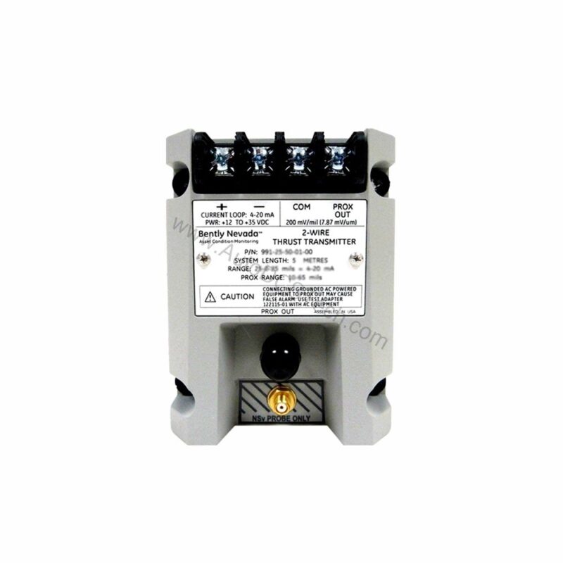
Introduction to the 991-25-50-02-CN
When axial thrust monitoring is critical, the 991-25-50-02-CN from Bently Nevada provides a reliable solution. This probe vibration transmitter is designed for continuous operation in demanding industrial environments. It converts proximity probe signals into a standard 4-20 mA current loop output, enabling seamless integration with existing control systems.
Part of the 991 series, this thrust transmitter is engineered for precision. Its full-scale option of 25-0-25 mils and 5.0-meter system length make it suitable for a wide range of rotating machinery applications. Whether you are upgrading an existing system or specifying new equipment, the 991-25-50-02-CN offers dependable performance.
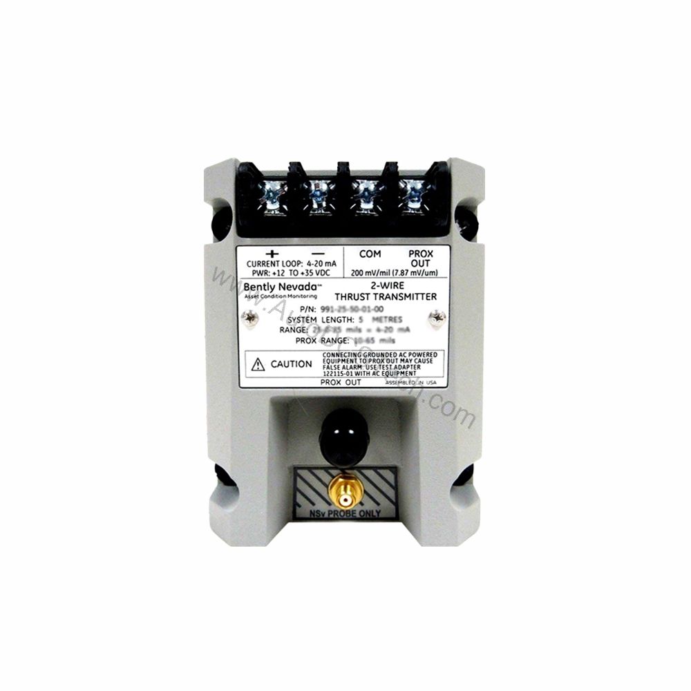
Key Features and Technical Specifications
The 991-25-50-02-CN is built to deliver accurate, real-time data. Below are the essential specifications extracted from the manufacturer's datasheet:
- Output Signal: 4-20 mA DC, two-wire configuration
- Power Requirement: +12 to +35 Vdc at transmitter terminals
- Linear Range: 0.25 to 1.65 mm for Prox Out; suitable for 0.6-0-0.6 mm or 25-0-25 mils current loop ranges
- Accuracy: Within ±1.5% over full-scale range (typical)
- Maximum Loop Resistance: 1,000 ohms including cable at 35 Vdc
- Current Limiting: 23 mA typical
- Operating Temperature: -35°C to +85°C (-31°F to +185°F)
- Storage Temperature: -51°C to +100°C (-60°F to +212°F)
- Weight: 0.43 kg (0.9 lbm)
One distinctive feature is the Not OK/Signal Defeat function. When a fault condition occurs, the output drops to less than 3.6 mA within 100 microseconds, providing an immediate warning to operators. This rapid response helps prevent machinery damage and unplanned downtime.
Applications and Use Cases
The 991-25-50-02-CN is specifically designed for axial thrust measurement in rotating equipment. Typical applications include turbines, compressors, and large pumps where axial shaft position is critical. Because it accepts a non-contacting 3300 NSv proximity probe, it is ideal for retrofitting existing bearing housings.
In a typical scenario, the transmitter is mounted on a DIN rail near the machine. The probe senses shaft position, and the transmitter converts that signal into a 4-20 mA loop that feeds into a PLC or DCS. This setup provides continuous monitoring without the need for separate signal conditioners.
Installation and Setup
Mounting the 991-25-50-02-CN is straightforward. The unit is designed for DIN rail mounting, simplifying panel installation. The bulkhead screw mounting option (Option 02) provides secure attachment in high-vibration environments.
Wiring is minimal: connect the probe and extension cable to the transmitter input, then wire the 4-20 mA output to your control system. Power is supplied via the same two-wire loop, so no separate power supply is needed. Ensure the loop resistance does not exceed 1,000 ohms at 35 Vdc to maintain accuracy.
For best results, verify that the probe gap is set within the linear range of 0.25 to 1.65 mm. The transmitter's zero and span are adjustable via non-interacting external controls, allowing field calibration without opening the enclosure.
Maintenance and Reliability
Routine maintenance is minimal. Periodically inspect the transmitter and probe cable for signs of wear or damage. Check that all connections remain tight, especially in environments with vibration or temperature extremes.
The operating temperature range of -35°C to +85°C ensures reliable performance in most industrial settings. The storage range of -51°C to +100°C protects the unit during transport or downtime. Regular verification of the output signal against a known reference can help detect drift before it becomes a problem.
Because the 991-25-50-02-CN is a safety-related component, always follow the manufacturer's manual for any maintenance procedures. Do not attempt to repair internal circuitry; replace the unit if it fails.
Compatibility and Integration
The 4-20 mA output is universally compatible with PLCs, DCSs, and standalone indicators. The two-wire configuration simplifies integration into existing loops. The transmitter accepts a 3300 NSv proximity probe, which is a common standard in Bently Nevada systems, ensuring easy replacement of older transmitters.
For new installations, confirm that the probe and extension cable lengths match the 5.0-meter system length option. This ensures accurate signal transmission without additional compensation.
Troubleshooting Common Issues
If the output signal is erratic, check the probe gap and cable integrity. If the output goes below 3.6 mA, a Not OK condition may be present—verify the probe connection and power supply. If the loop resistance exceeds 1,000 ohms, the signal may be attenuated; reduce cable length or use a larger gauge wire.
For persistent issues, consult the Bently Nevada documentation or contact AutoDCSTech for technical support.
Support and Availability
The 991-25-50-02-CN is available from AutoDCSTech, an industrial automation parts supplier. We maintain a ready inventory to support your maintenance and upgrade needs. Contact us for current pricing and lead times.