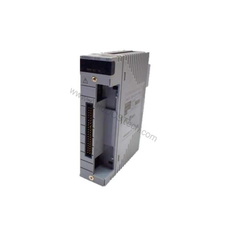
Introduction to the AAB841-S00
Industrial automation has evolved from simple relay logic to sophisticated distributed control systems. In modern plants, analog signals remain the backbone of process measurement and control. The AAB841-S00 from Yokogawa addresses this need with a compact, non-isolated analog I/O module. It provides 8 input channels for 1-5V signals and 8 output channels for 4-20mA signals, making it a versatile building block for control system upgrades.
This module is part of the Yokogawa AAB841 series, designed for use in distributed control systems. It offers a balanced combination of channel density and signal integrity, suitable for a wide range of industrial applications.
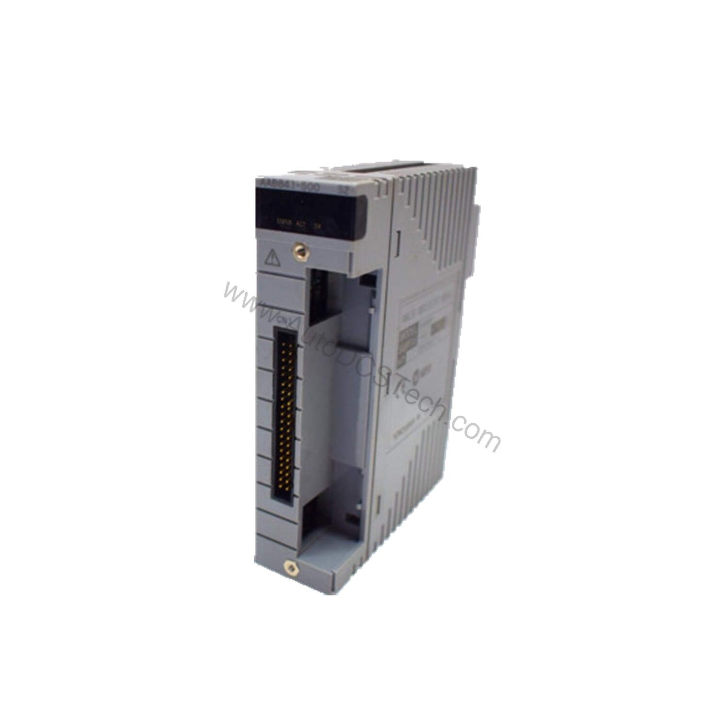
Key Features and Technical Specifications
The AAB841-S00 is engineered for reliable analog signal processing. Below are its core specifications, extracted directly from the datasheet.
| Parameter | Value |
|---|---|
| Input Signal | 1 to 5 V DC |
| Output Signal | 4 to 20 mA |
| Channels | 8 input / 8 output |
| Isolation | Non-isolated (differential input) |
| Allowable Common Mode Voltage | ±1 V or less |
| Input Resistance (Power ON) | 1 MΩ or larger |
| Input Resistance (Power OFF) | 340 kΩ or larger |
| Allowable Load Resistance | 0 to 750 Ω |
| Accuracy (Input) | ±16 µA |
| Accuracy (Output) | ±48 µA |
| Data Update Period | 10 ms |
| Input Step Response Time | 100 ms |
| Output Step Response Time | 40 ms |
| Transmitter Power Supply | 14.8 V or higher (at 20 mA), 26.4 V or less (at 0 mA) |
| Temperature Drift | ±0.1 %/10 °C |
| Max Current Consumption | 310 mA (5 V DC), 250 mA (24 V DC) |
| External Connection | Pressure clamp terminal, KS cable, MIL connector cable |
One distinctive feature is the transmitter power supply, which provides loop power for 2-wire transmitters. This simplifies wiring and reduces external power supply requirements, a key advantage in field installations.
Applications and Use Cases
The AAB841-S00 is suitable for a wide range of process control applications. Its 1-5V input is compatible with many field transmitters, while the 4-20mA output drives final control elements such as valves and actuators. Typical use cases include:
- Monitoring and controlling temperature, pressure, and flow loops.
- Interfacing with PLCs and DCS systems for analog signal conditioning.
- Retrofitting older analog control panels with modern digital systems.
Because the module supports both input and output on the same unit, it can serve as a compact I/O point in remote terminal units or marshalling cabinets.
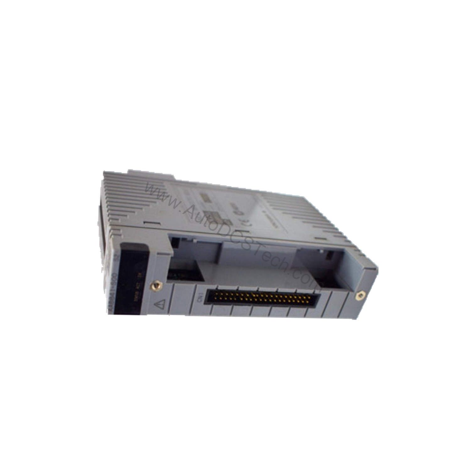
Installation and Setup
Proper installation ensures reliable operation. The AAB841-S00 uses pressure clamp terminals, KS cables, or MIL connector cables for external connections. When wiring, observe the polarity and ensure that the common mode voltage stays within ±1 V. For 2-wire transmitters, set the transmitter power supply pin per channel as needed. The module fits into standard Yokogawa I/O racks; refer to the system manual for slot placement and addressing.
Maintenance and Reliability
Routine maintenance is minimal. Periodically inspect the module for dust accumulation and ensure that all connectors are secure. The temperature drift of ±0.1 %/10 °C ensures stable performance across varying ambient conditions. Because the module is non-isolated, verify that the ground potential differences between field devices and the system do not exceed the specified common mode limit. Following these practices extends the service life and reduces unexpected downtime.
Compatibility and Integration
The AAB841-S00 is designed for Yokogawa control systems. It is compatible with the ATA4S single adapter, ATA4D dual redundant adapter, and various terminal boards such as AEA4D, MCM, MHM, MUB, TE16, and MHC. Cables KS1 and KS2 are also supported. This flexibility allows integration into both simplex and redundant architectures.
Troubleshooting and Common Issues
If the module does not respond, check the following:
- Verify that the input signal is within 1-5 V and the output load is within 0-750 Ω.
- Ensure that the common mode voltage does not exceed ±1 V; otherwise, the input may be corrupted.
- Check the transmitter power supply voltage: it should be at least 14.8 V at 20 mA and no more than 26.4 V at 0 mA.
- Inspect the external connections for loose terminations or damaged cables.
If the output current is inaccurate, verify the load resistance and the calibration of the receiving device.
Product Support and Availability
The AAB841-S00 is available from AutoDCSTech. Contact our team to confirm current stock and lead times. We provide fast, reliable service for industrial automation parts.