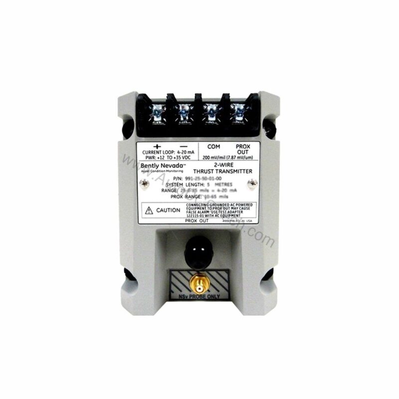
Why Accurate Thrust Measurement Matters
In rotating machinery, unplanned axial displacement can lead to catastrophic failure. How do you catch it early? The 991-25-50-03-00 from Bently Nevada provides continuous, reliable monitoring of thrust position, helping you avoid costly downtime.
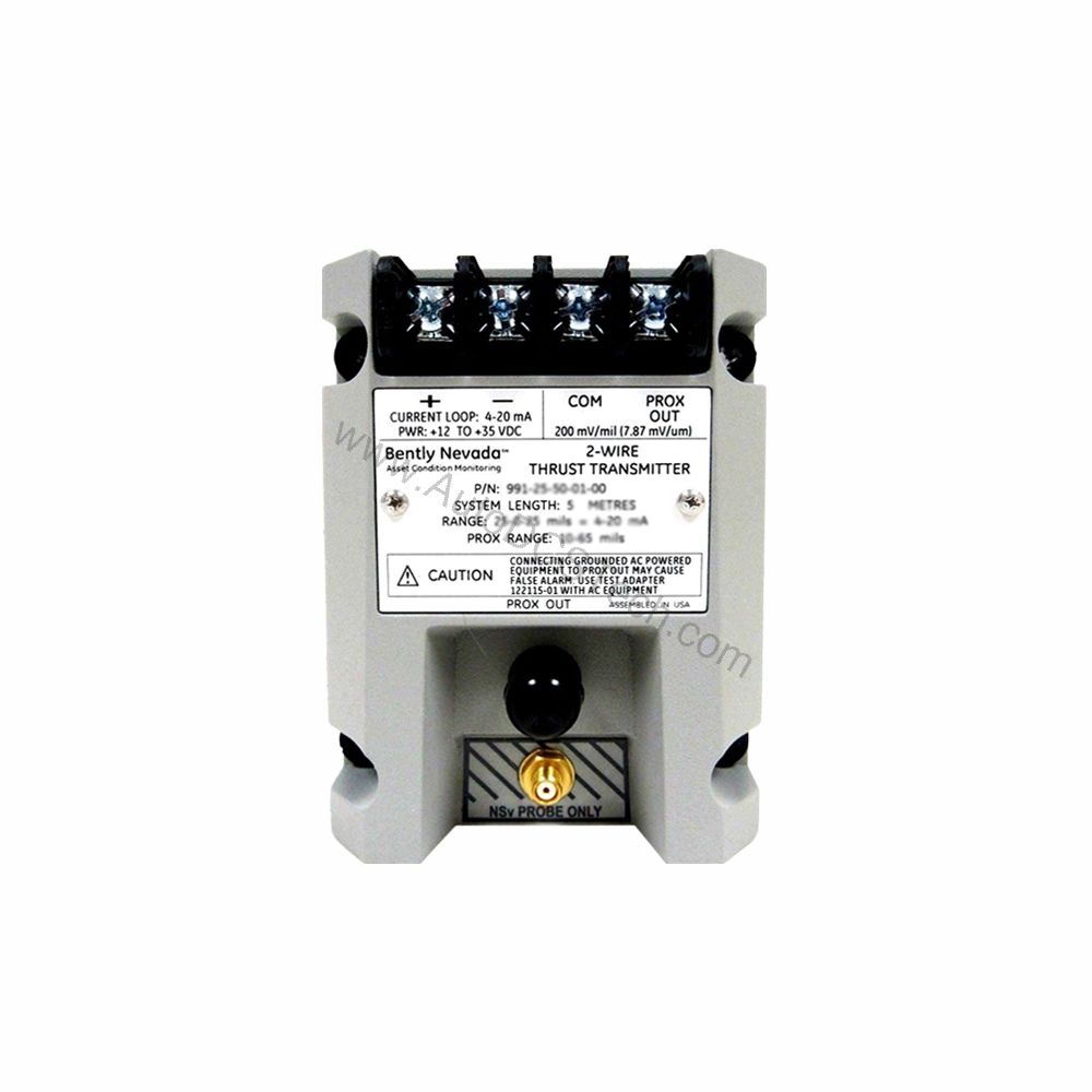
What Is the 991-25-50-03-00?
The 991-25-50-03-00 is a Probe Vibration Transmitter, specifically a Thrust Transmitter model 991. It is manufactured by Bently Nevada and made in the U.S.A. This unit is designed for axial (thrust) measurement and mounts on a standard DIN rail, simplifying installation in existing panels.
Key Features & Technical Specifications
- Full-Scale Range: 25-0-25 mils (0.6-0-0.6 mm).
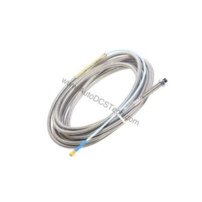
- System Length: 5.0 meters (16.4 feet) – includes probe and extension cable.
- Mounting Option: DIN clips and screws (option 03).
- Output Signal: 4-20 mA, 2-wire configuration.
- Power Requirement: +12 to +35 Vdc at the transmitter terminal.
- Linear Range: 0.25 to 1.65 mm for Prox Out; suitable for 0.6-0-0.6 mm or 25-0-25 mils current loop ranges.
- Accuracy: Within ±1.5% of full scale (typical).
- Maximum Loop Resistance: 1,000 Ω including cable at 35 Vdc.
- Current Limiting: 23 mA typical.
- Not OK/Signal Defeat: Output drops below 3.6 mA within 100 µs of a fault; restores within 0.1 seconds after fault clears.
- Operating Temperature: -35°C to +85°C (-31°F to +185°F).
- Storage Temperature: -51°C to +100°C (-60°F to +212°F).
- Weight: 0.43 kg (0.9 lbm).
The 4-20 mA output is industry-standard, allowing easy integration with PLCs, DCS, and SCADA systems. The non-interacting zero and span adjustments simplify calibration.
Applications & Use Cases
This transmitter is ideal for monitoring axial shaft position in turbines, compressors, and large pumps. In such applications, even minor thrust changes can indicate bearing wear or misalignment. By providing a continuous 4-20 mA signal, the 991-25-50-03-00 enables early detection of abnormal conditions, reducing the risk of unplanned outages.
Furthermore, its DIN-rail mount design makes it suitable for retrofit projects where panel space is limited. The 5.0-meter system length offers flexibility in routing the probe cable to the machine.
Installation & Setup
Mount the transmitter on a standard DIN rail using the provided clips and screws. Ensure the power supply delivers +12 to +35 Vdc at the transmitter terminals. Connect the 4-20 mA loop to your monitoring system, observing the maximum loop resistance of 1,000 Ω at 35 Vdc. For accurate readings, position the proximity probe according to the manufacturer's guidelines, maintaining the specified gap.
After installation, perform a zero and span calibration using the external adjustments. Verify the output corresponds to the actual shaft position.
Maintenance & Reliability
Routine inspection of the probe and cable is recommended to ensure reliable operation. Check for any physical damage or loose connections. The transmitter's wide operating temperature range (-35°C to +85°C) ensures dependable performance in harsh environments. The Not OK/Signal Defeat feature provides immediate fault indication, enhancing system safety.
Regularly verify the output signal against a known reference to maintain accuracy. Follow the manufacturer's manual for detailed maintenance procedures.
Compatibility & Integration
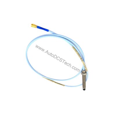
The 991-25-50-03-00 accepts one non-contacting 3300 NSv proximity probe and extension cable. Its 4-20 mA output is compatible with most industrial control systems, including PLCs and DCS. The two-wire configuration simplifies wiring and reduces installation cost.
Troubleshooting & Common Issues
If the output goes below 3.6 mA, a Not OK condition is indicated – check the probe connection and power supply. If the output is erratic, verify the probe gap and cable integrity. The current limiting (23 mA typical) protects the loop from overcurrent.
For persistent issues, consult the Bently Nevada documentation or contact AutoDCSTech for technical support.
Availability & Support
The 991-25-50-03-00 is available from AutoDCSTech. Contact us for current stock and lead times. Our team can assist with technical questions and ordering information.