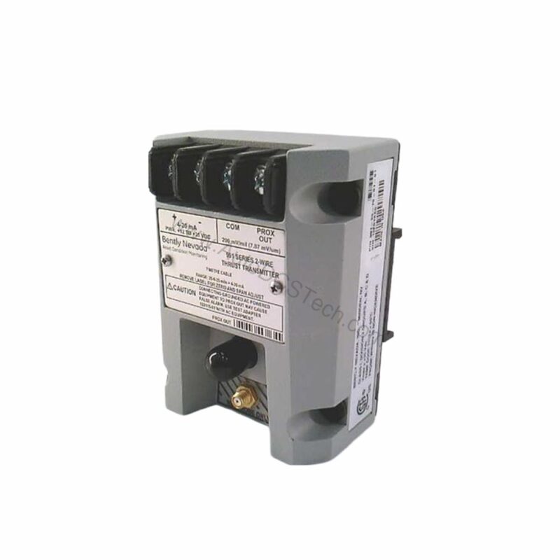
Why Choose the 991-25-70-02-01 for Axial Thrust Monitoring?
When rotating machinery experiences unexpected axial shaft movement, the consequences can be severe. The 991-25-70-02-01 from Bently Nevada provides a reliable solution for continuous thrust position monitoring. This probe vibration transmitter converts proximity probe signals into a standardized 4-20 mA output, enabling seamless integration with PLCs, DCS, and SCADA systems.
Designed for axial use, this transmitter is part of the Model 991 series, specifically configured with a 25-0-25 mils full-scale option. Its robust construction and precise linear range make it a trusted choice for critical turbomachinery protection.
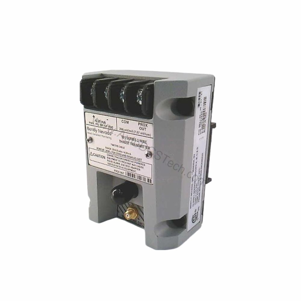
Key Features and Technical Specifications of the 991-25-70-02-01
The 991-25-70-02-01 offers a range of features that ensure accurate and reliable operation:
- Output Signal: 4-20 mA DC over the specified full-scale range in a 2-wire configuration.
- Power Requirement: +12 to +35 Vdc input at the transmitter terminal.
- Linear Range: 0.25 to 1.65 mm for Prox Out, suitable for 0.6-0-0.6 mm or 25-0-25 mils current loop linear ranges.
- Loop Accuracy: Within ±1.5% over the specified full-scale range (typical).
- Maximum Loop Resistance: 1,000 Ω including cable at 35 Vdc.
- Current Limiting: 23 mA typical.
- Zero and Span: Non-interacting external adjustments.
- Not OK/Signal Defeat: Output goes to less than 3.6 mA within 100 µs after a Not OK condition; restored within 0.1 seconds after removal.
- Mounting: DIN rail mount, with bulkhead screws option.
- Environmental Limits: Operating temperature -35°C to +85°C; storage temperature -51°C to +100°C.
- Weight: 0.43 kg (0.9 lbm).
One distinctive feature is the fast Not OK response. The 4-20 mA signal drops below 3.6 mA within 100 microseconds of a fault, allowing control systems to trigger alarms or shutdowns quickly, minimizing potential damage.
Applications and Use Cases for the 991-25-70-02-01
The 991-25-70-02-01 is primarily used in turbomachinery, including steam turbines, gas turbines, and large compressors. Its axial thrust measurement capability helps detect abnormal rotor position, preventing catastrophic contact between rotating and stationary parts. Additionally, it can be used in pumps and generators where axial movement is a concern.
For example, in a steam turbine, the transmitter continuously monitors thrust bearing wear. If the rotor shifts beyond safe limits, the 4-20 mA signal changes, prompting operators to take corrective action. This proactive approach reduces unplanned downtime and extends equipment life.
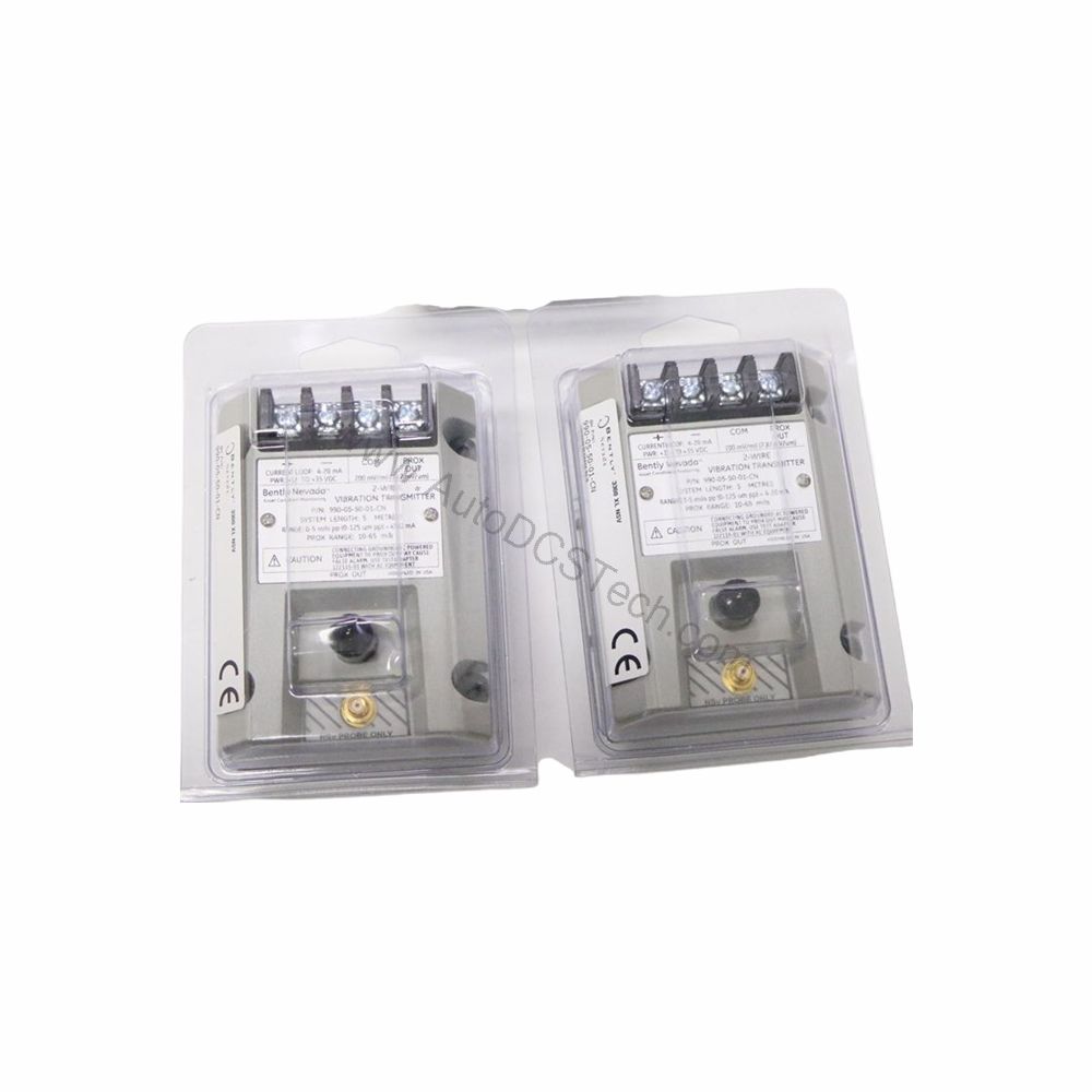
Installation and Setup Guide
Proper installation is critical for accurate thrust measurement. The 991-25-70-02-01 mounts on a DIN rail, simplifying panel integration. The bulkhead screw mounting option provides additional stability in high-vibration environments.
When wiring, ensure the power supply provides +12 to +35 Vdc at the transmitter terminals. Connect the 4-20 mA loop to the monitoring system, respecting the maximum loop resistance of 1,000 Ω to maintain accuracy. Use the non-interacting zero and span adjustments to calibrate the transmitter to the specific mechanical range.
Maintenance and Reliability Tips
Regular inspection of the transmitter and its connections is recommended to ensure long-term reliability. Check for loose wiring, corrosion, or physical damage. Verify the output signal periodically against a known reference to confirm accuracy.
Given the environmental limits, the transmitter can operate in harsh conditions, but exposure to extreme temperatures beyond -35°C to +85°C should be avoided. Following the manufacturer's manual for routine checks will help maintain optimal performance.
Compatibility and Integration
The 991-25-70-02-01 accepts one non-contacting 3300 NSv proximity probe and extension cable. Its 4-20 mA output is universally compatible with most control systems, including PLCs, DCS, and dedicated vibration monitors. This makes integration straightforward, whether upgrading an existing system or installing new equipment.
Troubleshooting Common Issues
If the output signal is erratic or out of range, first check the power supply voltage at the transmitter terminals. Ensure it is within +12 to +35 Vdc. Next, verify the loop resistance does not exceed 1,000 Ω, as higher resistance can cause voltage drops and inaccurate readings.
If the signal goes below 3.6 mA, the transmitter may be in a Not OK state. Investigate the probe and cable for damage or disconnection. After resolving the issue, the output should restore within 0.1 seconds.
Product Support and Availability
The 991-25-70-02-01 is available from AutoDCSTech. Please verify current lifecycle status and availability with AutoDCSTech before ordering. Our team can assist with technical questions and ensure you receive the right part for your application.