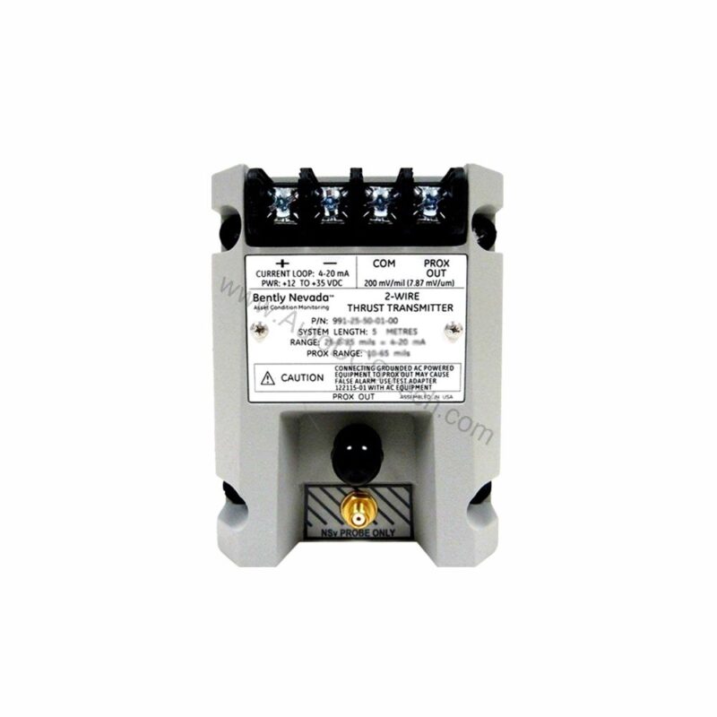
991-25-50-01-05 Overview: Precision Thrust Monitoring
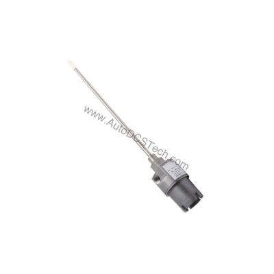
When axial shaft position drifts beyond safe limits, the 991-25-50-01-05 Bently Nevada probe vibration transmitter provides early warning. This DIN-rail mounted device converts proximity probe signals into a standard 4-20 mA loop, enabling seamless integration with PLCs and DCS systems.
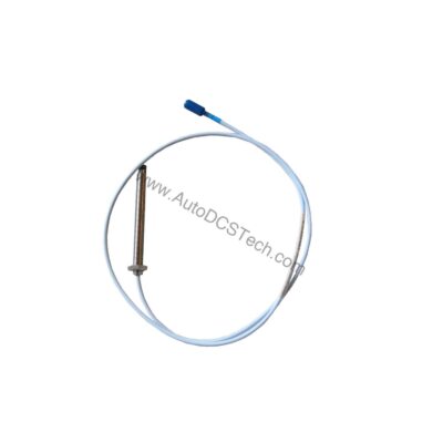
Designed for thrust measurement, the 991-25-50-01-05 accepts one non-contacting 3300 NSv proximity probe and extension cable. Its linear range spans 0.25 to 1.65 mm for prox output, supporting 0.6-0-0.6 mm or 25-0-25 mils current loop ranges. This flexibility makes it suitable for a variety of rotating machinery applications.
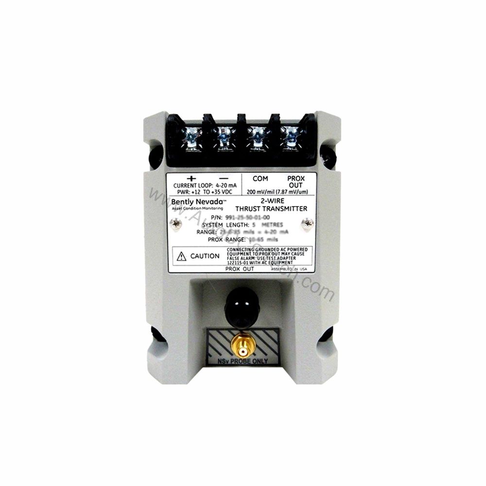
Key Features and Technical Specifications
The 991-25-50-01-05 offers robust performance in demanding environments. Its key specifications include:
- Output Signal: 4-20 mA DC, two-wire configuration
- Power Requirement: +12 to +35 Vdc at transmitter terminals
- Loop Accuracy: Within ±1.5% of full scale (typical)
- Maximum Loop Resistance: 1,000 Ω including cable at 35 Vdc
- Current Limiting: 23 mA typical
- Operating Temperature: -35°C to +85°C (-31°F to +185°F)
- Storage Temperature: -51°C to +100°C (-60°F to +212°F)
- Weight: 0.43 kg (0.9 lbm)
The transmitter's Not OK/Signal Defeat function forces output below 3.6 mA within 100 µs of a fault, ensuring fail-safe operation. This rapid response minimizes risk of undetected failures, reducing potential downtime costs.
Cost-Efficiency Through Reliable Design
From a cost perspective, the 991-25-50-01-05 reduces total ownership expenses. Its DIN-rail mounting simplifies installation, cutting labor time. The two-wire loop configuration lowers wiring material costs. Moreover, the ±1.5% accuracy ensures precise monitoring, preventing costly false trips or missed alarms.
With a wide operating temperature range, the transmitter withstands harsh industrial environments, minimizing replacement frequency. The current limiting feature protects the loop, avoiding damage to downstream equipment and reducing repair costs.
Installation and Setup
Mounting the 991-25-50-01-05 is straightforward. The 35 mm DIN-rail clips allow quick snap-on installation. Connect the proximity probe and extension cable to the transmitter input. Then wire the 4-20 mA output to your monitoring system, ensuring the power supply provides +12 to +35 Vdc at the terminals.
Zero and span adjustments are non-interacting, simplifying calibration. Verify the full-scale option matches your application: the -25 option corresponds to 25-0-25 mils. The system length option -50 indicates a 5.0 meter (16.4 feet) cable, which must be considered during layout.
Maintenance and Reliability
Routine inspection of the 991-25-50-01-05 is minimal. Periodically verify the output signal responds correctly to shaft movement. Check that the DIN-rail clips remain secure and that the probe cable is not damaged. The transmitter's sealed design protects against dust and moisture, enhancing long-term reliability.
Because the device is not safety-rated, follow standard industrial maintenance practices. Always consult the Bently Nevada manual for detailed procedures. Regular checks help avoid unexpected failures, contributing to lower maintenance costs over the equipment's lifespan.
Support and Availability
The 991-25-50-01-05 is available through AutoDCSTech. As an industrial automation parts supplier, AutoDCSTech ensures genuine Bently Nevada products. Contact us for current stock and lifecycle status. We provide prompt support to keep your operations running efficiently.