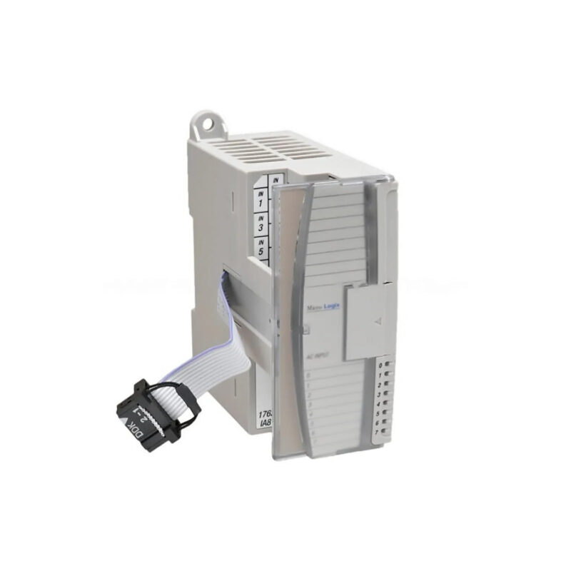
Product Overview
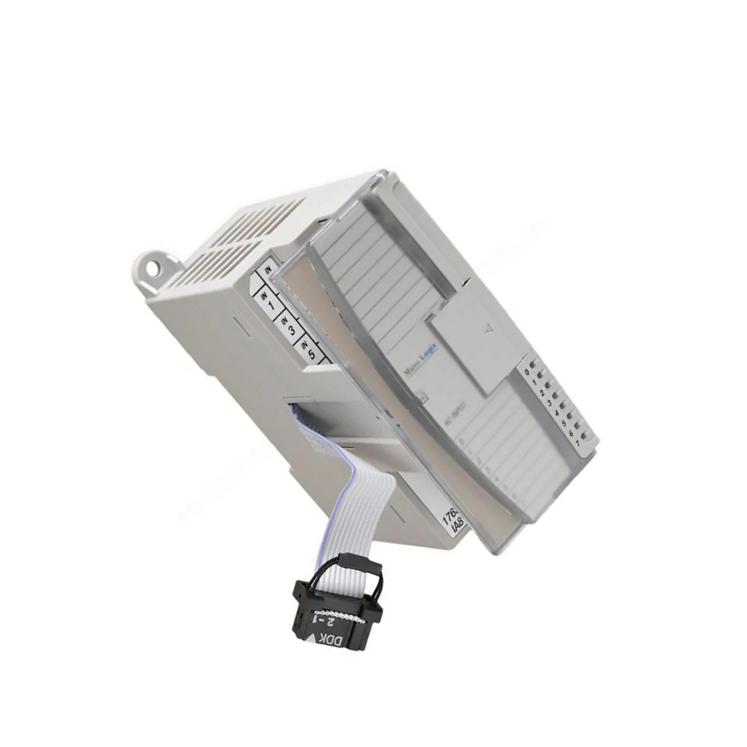
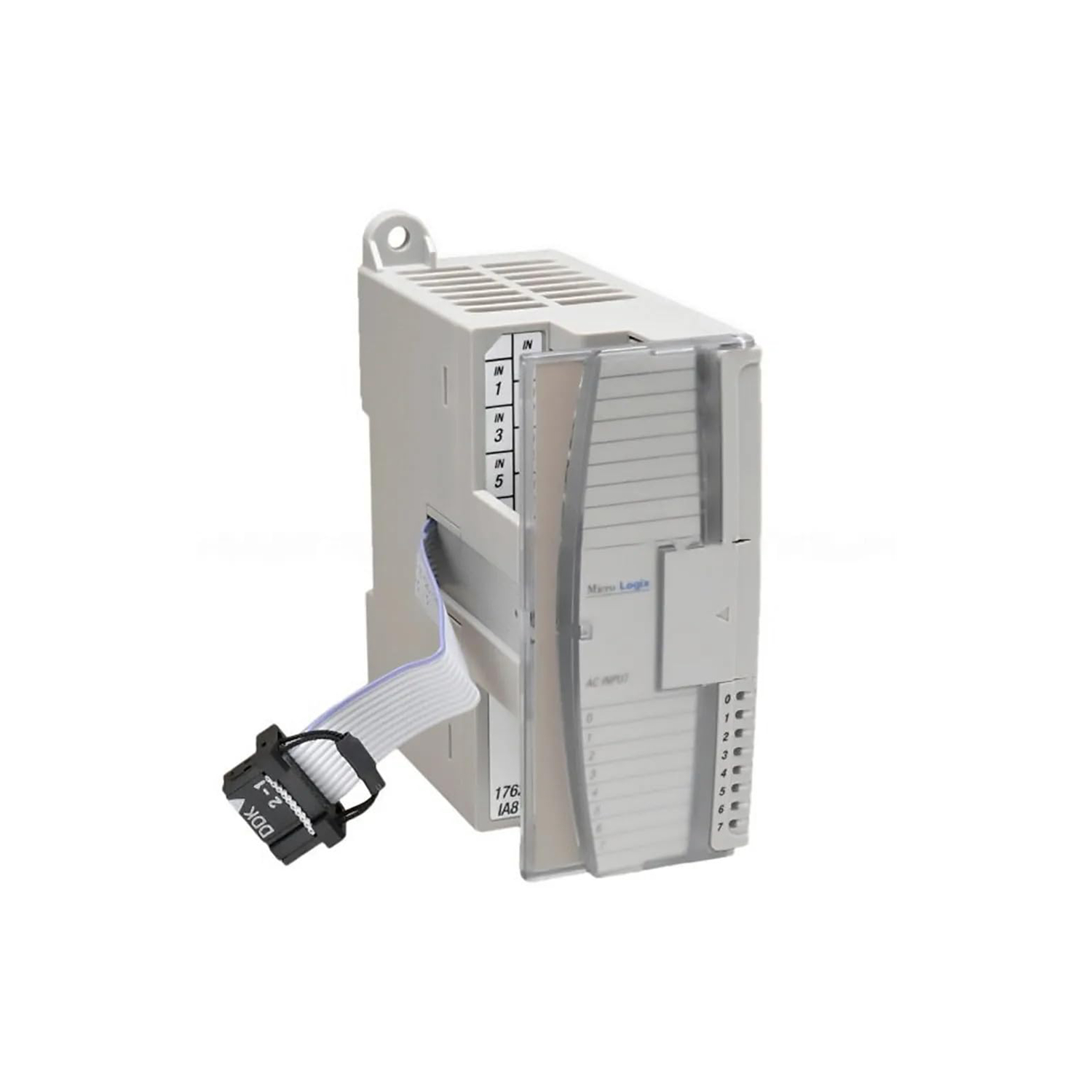
The Allen-Bradley 1762-OB8 is a solid-state expansion module from the MicroLogix 1200 series, manufactured by Rockwell Automation. It provides 8 digital DC sourcing outputs for expanding the I/O capacity of a MicroLogix 1200 controller. Designed for industrial environments, this module mounts on a DIN rail and operates within a voltage range of 20.4 to 26.4 Volts DC. Its solid-state design ensures fast, maintenance-free switching for demanding applications.
Technical Specifications Breakdown
Key parameters for the 1762-OB8 are listed below for quick reference:
| Feature | Specification |
|---|---|
| Manufacturer | Rockwell Automation |
| Brand | Allen-Bradley |
| Part Number | 1762-OB8 |
| Series | MicroLogix 1200 |
| Product Type | Solid-State Expansion Module |
| Operating Voltage Range | 20.4-26.4V DC |
| Outputs | 8 |
| Voltage Category | 24V DC |
| Mounting | DIN Rail |
| Backplane Current | 115 mA at 5 Volts |
Industry Applications
In packaging machinery, the 1762-OB8 can handle up to 0.5A per output, switching loads with a maximum ON-state voltage of 1.0 Volts DC. For material handling systems, its 2A intermittent surge capability (10ms duration, repeatable every 2 seconds) accommodates inrush currents from small motors or clutches. The module's aggregate current of 4A per module supports multiple outputs active simultaneously, reducing the need for additional I/O racks.
Installation & Setup Guidance
Mount the 1762-OB8 on a standard DIN rail adjacent to the MicroLogix 1200 controller. Ensure the backplane connector aligns properly and secure the module with the locking tab. The operating voltage range of 20.4 to 26.4 Volts DC must be supplied from a regulated power source; verify polarity before connecting loads. Each output is sourcing type, meaning it switches the positive side of the DC supply. Use copper wiring rated for at least 0.5A per point and observe the maximum power supply distance of 6 module lengths to avoid voltage drop. Do not exceed the backplane current of 115 mA at 5 Volts when adding modules to the system.
Maintenance & Reliability
The solid-state design of this module eliminates mechanical contact wear, reducing maintenance needs. Operate within the temperature range of 0 to 55 degrees Celsius and non-condensing humidity of 5 to 95% for optimal performance. Store the module at -40 to 85 degrees Celsius when not in use. Periodically inspect connections for tightness and cleanliness, especially in dusty environments. The module withstands 30G shock and 5G vibration at 500 Hertz, making it suitable for applications near vibrating machinery.
The Evolution of Compact Control
Industrial automation has shifted toward modular, space-saving designs that allow manufacturers to scale I/O without replacing entire controllers. The Allen-Bradley MicroLogix 1200 series exemplifies this trend, offering expansion modules that integrate with existing systems. The 1762-OB8 solid-state expansion module is a key component for applications requiring reliable digital output switching in a compact form factor.
Compatibility & Integration
The 1762-OB8 is designed exclusively for the MicroLogix 1200 controller series. It connects via the backplane and is recognized automatically by the controller software. The module provides group-to-backplane isolation tested at 1200 Volts AC or 1697 Volts DC for 1 second, ensuring electrical safety between outputs and the control system. Verify firmware compatibility with your controller revision before installation.
Selection Guide & Purchasing Advice
When selecting expansion I/O for your MicroLogix 1200 system, consider the number of outputs needed and the load current per point. The 1762-OB8 offers 8 outputs with a maximum load of 0.5A each, suitable for most discrete DC loads. For higher current requirements, consider alternative modules. AutoDCSTech stocks the 1762-OB8 and can advise on availability and lifecycle status. Contact our team for pricing and lead times.
Troubleshooting & Common Issues
If outputs fail to energize, first verify the operating voltage is within 20.4 to 26.4 Volts DC. Check the backplane connection and ensure the module is properly seated. Use a multimeter to measure the ON-state voltage at the output terminal; it should be 1.0 Volts DC maximum when the output is active. If leakage current is suspected, measure with the load disconnected; maximum leakage is 1.0 mA. For intermittent faults, inspect for loose wiring or environmental contaminants. Signal delays are minimal: 0.1 milliseconds ON-state and 1.0 milliseconds OFF-state at resistive loads.
Availability & Condition at AutoDCSTech
| Part Number | 1762-OB8 |
|---|---|
| Availability | In Stock |
| Condition | New |
| Warranty | One Year |
| Origin | US |