Product Overview
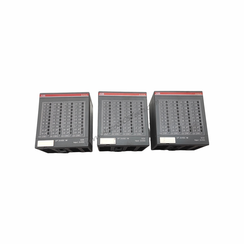
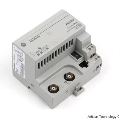
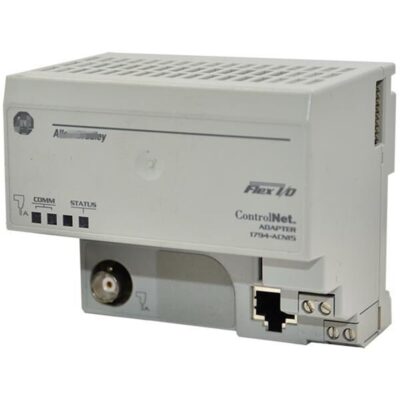
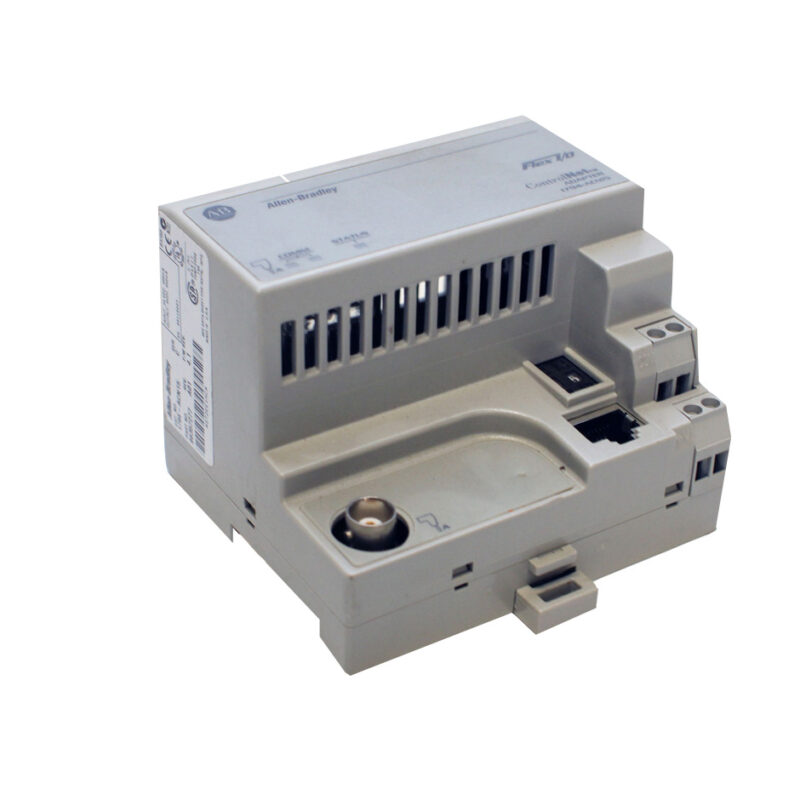
The 1794-IB32 is a Flex I/O DC input module from Allen-Bradley, part of the Rockwell Automation portfolio. It belongs to the Flex I/O product family of distributed I/O components. This module serves as an input interface, allowing field instruments and electrical devices to integrate with any automated control system or process. With 32 sinking input channels, it supports high-density applications while maintaining robust performance.
Technical Specifications Breakdown
Key parameters for the 1794-IB32 are listed below for quick reference:
| Feature | Specification |
|---|---|
| Number of Inputs | Thirty-Two (32), sinking inputs |
| On-state Voltage (min) | 19.2 Volts DC |
| On-state Voltage (max) | 31.2 Volts DC |
| On-state Current (minimum) | 2.0 milliamps |
| On-state Current (maximum) | 6.0 milliamps |
| Off-state Voltage (maximum) | 5 Volts DC |
| Off-state Current (maximum) | 1.5 milliamps |
| Nominal Input Impedance | 22.2 kΩ |
| Flexbus Current | 30 milliamps at 5 Volts DC |
| Power Dissipation | 6.0 Watts at 31.2 Volts DC maximum |
| Operating Temperature | 0 to 55 °C (32 to 131 °F) |
| Storage Temperature | -40 to 85 °C (-40 to 185 °F) |
| Vibration | 5g @ 10 to 500 Hz |
| Operating Shock | 30 g |
| Dimensions | 94 x 94 x 69 mm (3.7 x 3.7 x 2.7 in.) |
| Mounting | DIN Rail |
| Indicators | 32 Yellow status indicators |
Industry Applications
For example, in a packaging facility, 32 proximity sensors can connect to a single 1794-IB32, reducing wiring complexity and cabinet space. In material handling, limit switches and float switches integrate easily, thanks to the wide on-state voltage range of 19.2 to 31.2VDC. The sinking input configuration simplifies integration with common DC sensors, lowering overall system cost.
Installation & Setup Guidance
Mount the 1794-IB32 on a DIN rail using the provided slot on the terminal base. Compatible terminal bases include 1794-TB3, 1794-TB3S, 1794-TBN, 1794-TB3K, 1794-TB3SK, and 1794-TBNK. Wire size is determined by the installed terminal base, so refer to its specifications. The keyswitch position is set to 2 for proper alignment. Ensure the module attaches securely to the terminal base for reliable electrical connections. The module supports removal and insertion under power when used with compatible bases.
Maintenance & Reliability
Inspect the module periodically for dust accumulation or loose connections. The open-style enclosure requires a clean, dry environment. Operating temperature range is 0 to 55 °C, and storage temperature is -40 to 85 °C. The module withstands vibration of 5g at 10 to 500 Hz and operating shock of 30 g. For long-term reliability, verify that the ambient conditions remain within these limits.
Compatibility & Integration
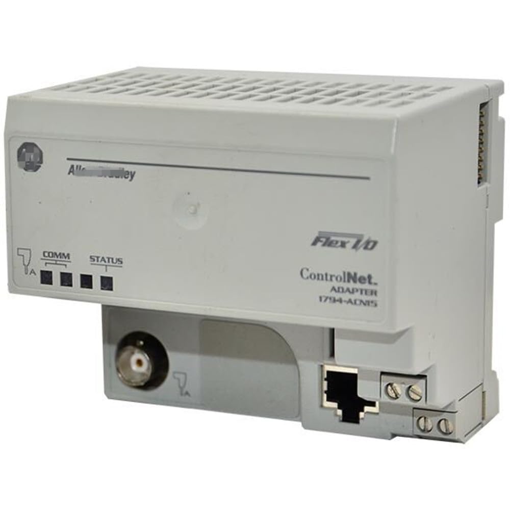
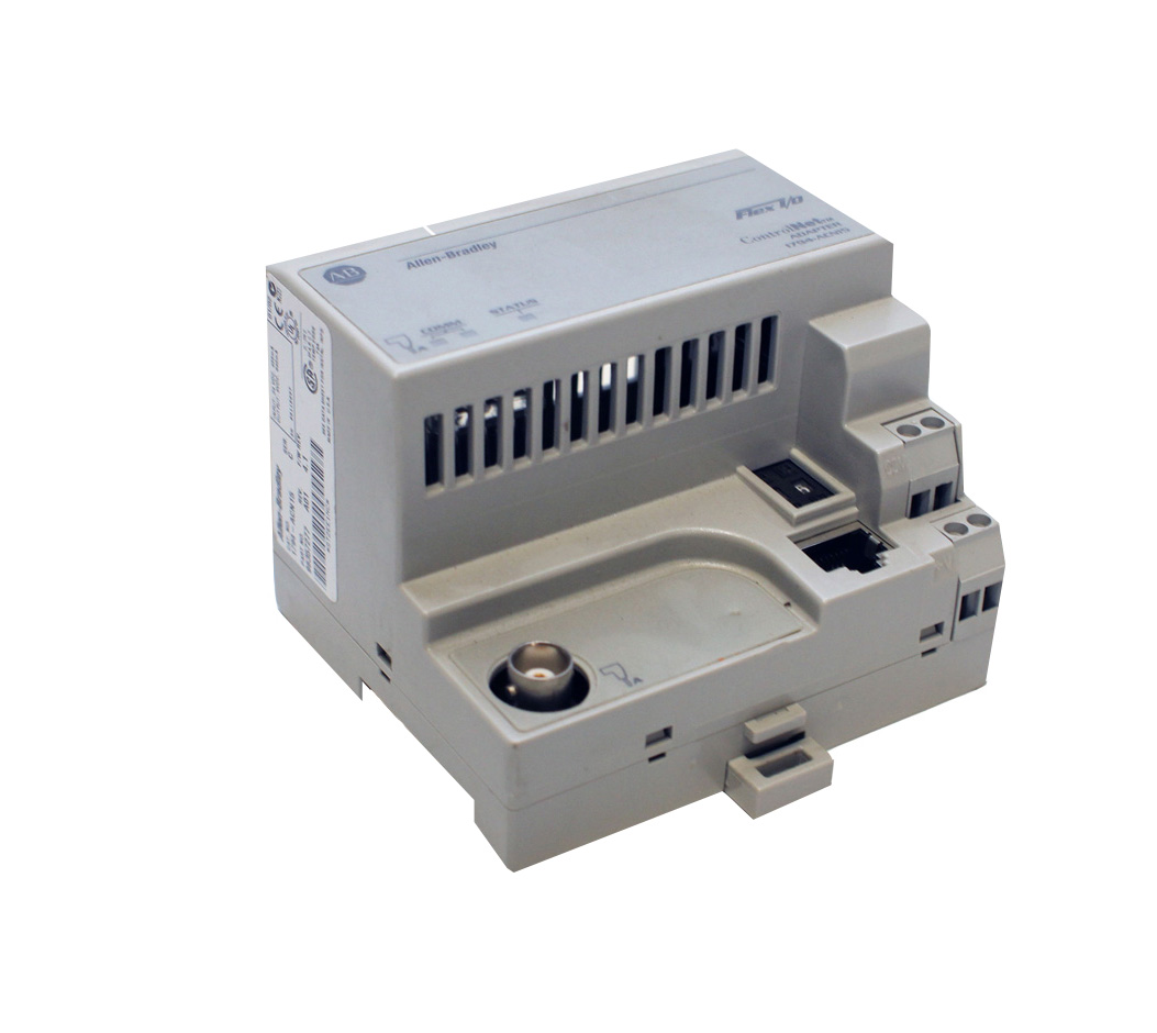
The 1794-IB32 works with Flex I/O communication adapters, including Ethernet, ControlNet, Remote I/O, and others. It is compatible with terminal bases such as 1794-TB32, 1794-TB32S, 1794-TB62DS, and 1794-TB62EXD4X15 for high-density wiring. The module's FlexBus current of 30 milliamps at 5 Volts DC ensures low power consumption from the backplane.
Selection Guide & Purchasing Advice
When selecting the 1794-IB32, consider the number of input devices and voltage requirements. At AutoDCSTech, we stock genuine Allen-Bradley parts with fast shipping. Please verify current lifecycle status and availability with AutoDCSTech before ordering.
Troubleshooting & Common Issues
If an input channel fails to respond, check the LED indicator: 32 yellow status indicators show channel activity. An unlit LED may indicate a wiring fault or sensor issue. Verify the on-state voltage is between 19.2 and 31.2VDC. For off-state conditions, ensure voltage stays below 5 Volts DC and current below 1.5 milliamps. If multiple channels fail, inspect the terminal base connection and FlexBus power.
Availability & Condition at AutoDCSTech
| Part Number | 1794-IB32 |
|---|---|
| Availability | In Stock |
| Condition | New |
| Warranty | One Year |
| Origin | US |