Introduction
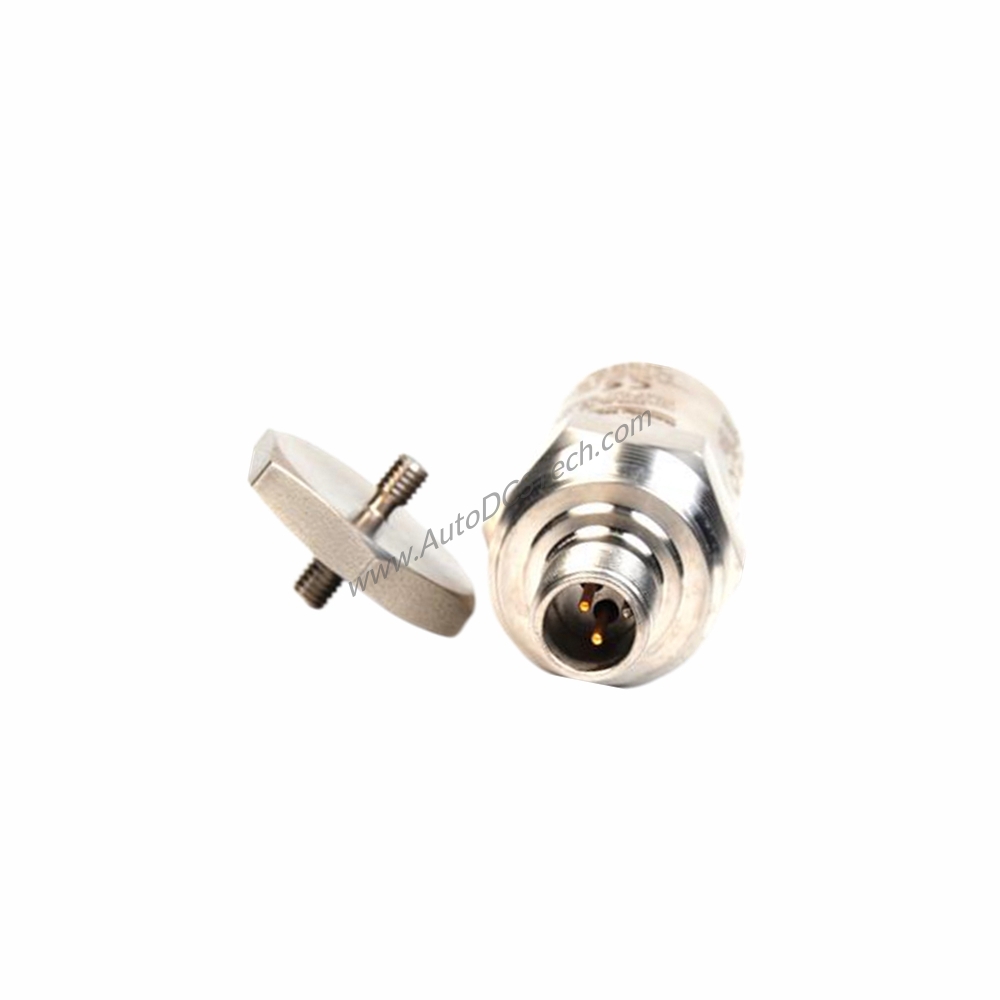
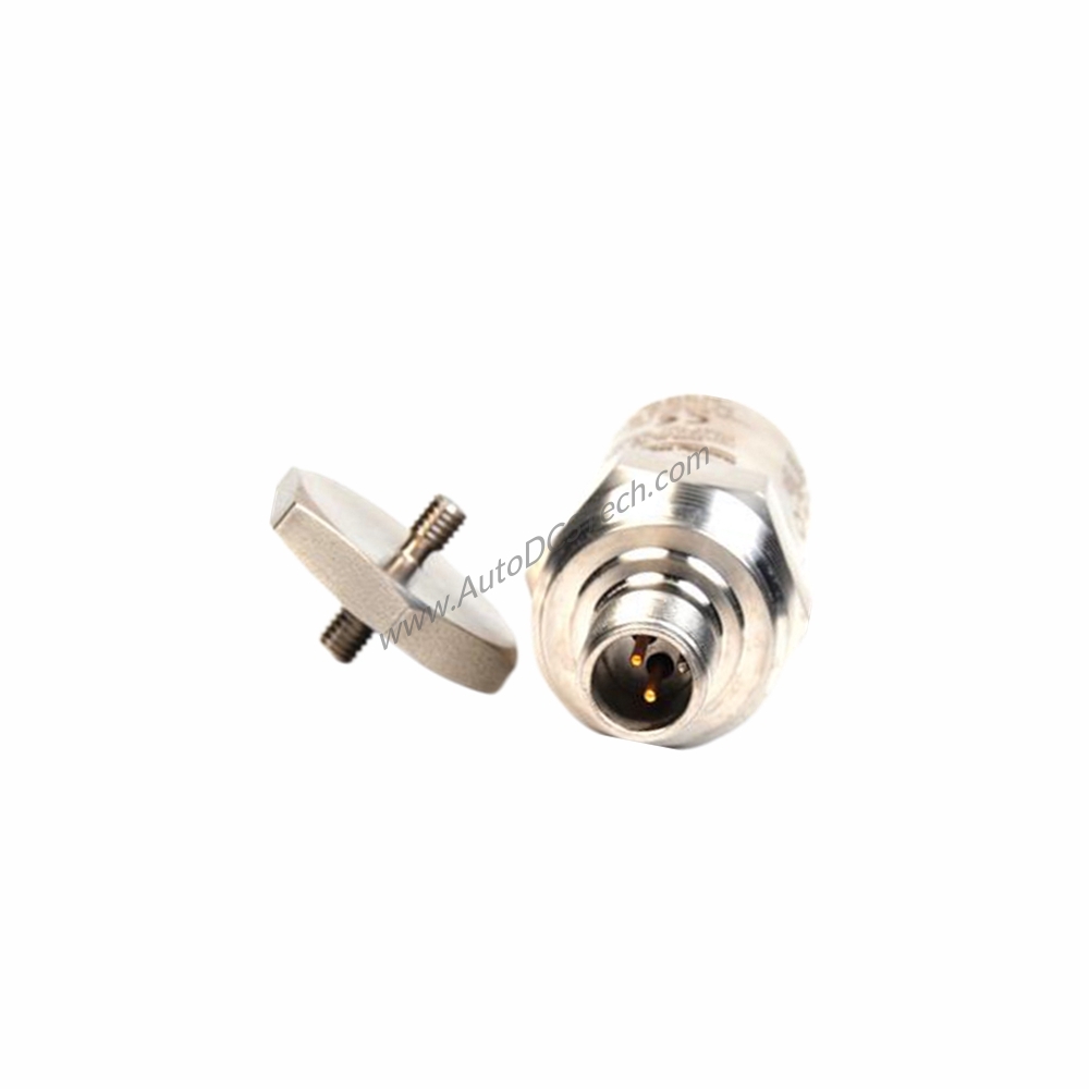
The Bently Nevada 190501-07-00-01 Velomitor CT Velocity Transducer provides the precise, reliable vibration data needed to detect early bearing wear and imbalance before failures occur. Designed for continuous monitoring in the most demanding industrial environments, this velocity transducer delivers consistent performance under extreme temperatures and hazardous conditions.
Technical Specifications Breakdown
The 190501-07-00-01 offers a sensitivity of 3.94 mV/mm/s (100 mV/in/s) ±5%, ensuring accurate velocity measurements across a wide amplitude range. Its frequency response spans 3.0 Hz to 900 Hz (180 to 54,000 cpm) ±1.0 dB, with an extended range of 1.5 Hz to 1.0 kHz (90 to 60,000 cpm) ±3.0 dB, making it suitable for low-speed to high-speed machinery. The output bias voltage is 10.1 Vdc ± 1.0 Vdc (Pin A referenced to Pin B), and the dynamic output impedance is less than 400 Ω typical. Amplitude linearity is ±2% to 63.5 mm/s pk (2.5 in/s pk), while the mounted resonant frequency is 9 kHz minimum (stud mounted, except quick disconnect). These parameters ensure the transducer captures vibration signals with high fidelity, enabling effective condition monitoring.
Industry Applications
For example, on a steam turbine in a Class I, Division 1 environment, the 190501-07-00-01 provides continuous velocity monitoring to detect shaft vibration and bearing degradation. Its ATEX/IECEx/CSA (Class I, Zone 0/1) certification allows direct installation in explosive atmospheres without additional barriers.
Installation & Setup Guidance
Mount the 190501-07-00-01 using the provided 3/8-in 24 to 3/8-in 24 plate stud option. Apply a mounting torque of 4.5 N-m ± 0.6 N-m (40 in–lbf ± 5 in-lbf) to ensure proper coupling. The transducer can be mounted at any angle, providing flexibility for tight spaces. Use the MIL-C-5015 connection interface with a maximum cable length of 305 metres (1,000 ft.) of part number 02173006 cable without signal degradation. Verify polarity: Pin A goes positive with respect to Pin B when velocity is from base to top. Follow installation drawing 167536 for intrinsic safety compliance.
Maintenance & Reliability
The internal electronics are isolated from the case, reducing ground loop issues. With a shock limit of 5000 g pk maximum and magnetic field susceptibility less than 0.0068 mm/s/gauss (0.268 mil/s/gauss) @ 50 gauss, 50-60 Hz, this transducer withstands harsh industrial conditions. No periodic maintenance is required beyond visual inspection of the cable and connector integrity. The broad band noise floor is only 0.229 mm/s (0.009 in/s) pk, ensuring clean signals for early fault detection. This reliability translates to reduced unplanned downtime and lower total cost of ownership.
Selection Guide & Purchasing Advice
Before ordering, verify that your application requires a velocity transducer with the sensitivity and frequency response of the 190501-07-00-01. Confirm the agency approval option (01) matches your hazardous area classification: CSA/NRTL/C (Class I, Division 1) and ATEX/IECEx/CSA (Class I, Zone 0/1). AutoDCSTech stocks this model and can advise on compatible cables and mounting hardware. Contact our team to ensure the 190501-07-00-01 meets your specific machinery monitoring needs.
Availability & Condition at AutoDCSTech
| Part Number | 190501-07-00-01 |
|---|---|
| Availability | In Stock |
| Condition | New |
| Warranty | One Year |
| Origin | US |