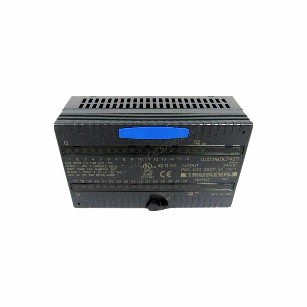
Product Introduction
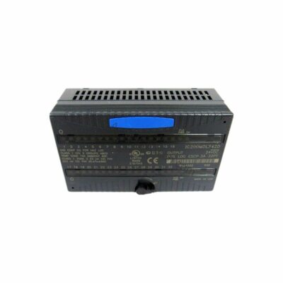
When industrial automation systems demand reliable discrete I/O in a compact form factor, the GE IC200MDD845 Mixed Module delivers a proven solution. Part of the VersaMax I/O series, this module combines 16 positive logic inputs and 8 individually isolated Form A relay outputs into a single unit. Designed for distributed I/O stations or native CPU-based control systems, it simplifies wiring and reduces panel space. The IC200MDD845 draws a maximum of 270 mA from the backplane, making it energy-efficient for multi-module racks.
Technical Specifications Breakdown
The IC200MDD845 offers 24 I/O points total: 16 inputs and 8 outputs. Inputs accept a nominal 24 VDC signal with a range of 18-30 VDC. On-state current is 2.0-5.5 mA, while off-state current is 0-0.5 mA. The eight outputs are Form A relay contacts, each rated for 2.0 A at 5-265 VAC (resistive) or 2.0 A at 5-30 VDC (resistive), and 0.2 A at 31-125 VDC (resistive). Output channels are individually isolated, enhancing system reliability. The module requires an IC200CHS series carrier base and supports channel-to-channel isolation for outputs only. It does not include internal fuses or snubbers.
Industry Applications
In discrete manufacturing, the IC200MDD845 handles machine control tasks like monitoring limit switches and driving solenoid valves. Its 16 inputs can detect part presence, while the 8 relay outputs actuate pneumatic cylinders. For material handling systems, the module's individually isolated outputs prevent fault propagation, reducing downtime. The 0.5 ms ON response time and 10 ms OFF response time suit high-speed sorting lines. In packaging machinery, the mixed I/O configuration eliminates the need for separate input and output modules, lowering overall system cost.
Installation & Setup Guidance
Mount the IC200MDD845 onto a compatible IC200CHS carrier base. Ensure backplane power is off during installation. Wire inputs using 24 VDC positive logic: connect the common to 0 VDC and signal wires to the input terminals. For outputs, connect the Form A relay contacts to the load circuit, respecting the voltage and current limits. Each output channel is isolated, so separate power sources can be used for different loads. After wiring, power up the backplane and verify the OK LED illuminates. Check individual channel LEDs to confirm correct I/O status.
Maintenance & Reliability
Periodically inspect the IC200MDD845 for dust accumulation on the ventilation slots. Ensure ambient temperature stays within the module's operating range (not specified, but typical for industrial enclosures). Check relay output contacts for signs of arcing or wear, especially under high inrush loads. The module's LED indicators provide quick visual diagnostics: a steady OK LED confirms backplane power; channel LEDs show active I/O states. For long-term reliability, avoid exceeding the 2.0 A per output rating. Follow the manufacturer's safety manual for any maintenance procedures.
Compatibility & Integration
It works with VersaMax native CPU modules or as part of a distributed I/O station connected to a PLC via the backplane. The module does not include built-in communication protocols; it relies on the carrier base for backplane communication. Ensure the carrier base supports the required number of I/O modules. The module's 270 mA backplane current draw must be accounted for in the power supply budget.
Selection Guide & Purchasing Advice
Before ordering the IC200MDD845, verify that your system uses VersaMax I/O architecture. Confirm the carrier base model (IC200CHS series) is available. Check that the backplane power supply can handle the module's 270 mA maximum draw plus other modules. The module is suitable for applications needing 16 inputs and 8 relay outputs in one unit. For higher output current requirements, consider external relays. AutoDCSTech stocks the IC200MDD845 and compatible accessories. Contact our team to confirm availability and lifecycle status before placing an order.
Troubleshooting & Common Issues
If the OK LED is off, check backplane power and carrier base connection. If an input channel LED does not light when the sensor is active, verify the 24 VDC supply and wiring polarity. For output channels that fail to energize, measure the relay coil voltage and confirm the load is within the 2.0 A rating. If an output channel remains stuck, cycle power to reset the relay. The module does not have internal fuses; use external fusing for each output circuit to protect against short circuits. For persistent issues, consult the VersaMax user manual.
Availability & Condition at AutoDCSTech
| Part Number | IC200MDD845 |
|---|---|
| Availability | In Stock |
| Condition | New |
| Warranty | One Year |
| Origin | US |