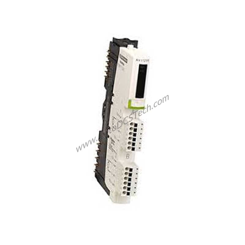
Technical Specifications Breakdown
The STBEPI2145K operates on a 24 V DC supply voltage with defined input voltage limits: 15...30 V at state 1 and -3...5 V at state 0. It guarantees a state 0 current of ≤ 0.5 mA and a state 1 current of ≥ 2 mA, ensuring precise signal detection. The output channels also use 24 V DC, and the kit includes integrated protection features: a time-lag 10 A fuse on the power distribution module, plus overload and short-circuit protection. Current consumption is ≤ 100 mA at 24 V DC for the sensor bus and ≤ 220 mA at 24 V DC for the actuator bus during 150 ms bursts. For the logic bus, it draws 100 mA at 5 V DC. The kit supports both cold swapping and hot swapping for standard NIMs, with a fallback state 0 for basic NIMs and user-configurable fallback for standard NIMs.
Industry Applications
The 12 input channels monitor limit switches or sensors, while the 8 output channels command contactors or relays. For example, in a bottling line, the STBEPI2145K can handle parallel signals from multiple stations, reducing wiring complexity and improving system response. Its hot swapping capability minimizes downtime during maintenance or upgrades.
Installation & Setup Guidance
Mount the STBEPI2145K on a STBXBA3000 base using the included terminal spring clamp connector and terminal screw type connector. Connect the power distribution module STBPDT3100 or STBPDT3105 for supply voltage. Use the four RJ45 connectors for network wiring. Ensure the module is properly seated and the green RDY LED illuminates after power-up. For hot swapping, verify that the NIM is a standard type to enable live replacement.
Maintenance & Reliability
The STBEPI2145K is built for harsh industrial conditions, operating from -25 to 70 °C without derating and storing from -40 to 85 °C. It withstands vibration up to 3 gn at 58...150 Hz on standard DIN rails and shock resistance of 30 gn for 11 ms. The IP20 protection rating suits clean, dry control cabinets. Regularly inspect the green status LEDs (RDY, S1, S2, and output LEDs) and the red ERR LED to quickly identify module faults. The integrated fuse and protection circuits reduce the risk of damage from overloads or short circuits.
What Is the STBEPI2145K?
Compatibility & Integration
This kit is designed for Modicon STB distributed I/O solutions and is compatible with TeSys Quickfit and TeSys U motor starters. It works with standard NIMs for hot swapping and basic NIMs for fallback state 0. The four RJ45 connectors facilitate easy integration into existing control networks. The kit carries CE, UL, CSA, and FM Class 1 Division 2 certifications, ensuring compliance with international standards.
Selection Guide & Purchasing Advice
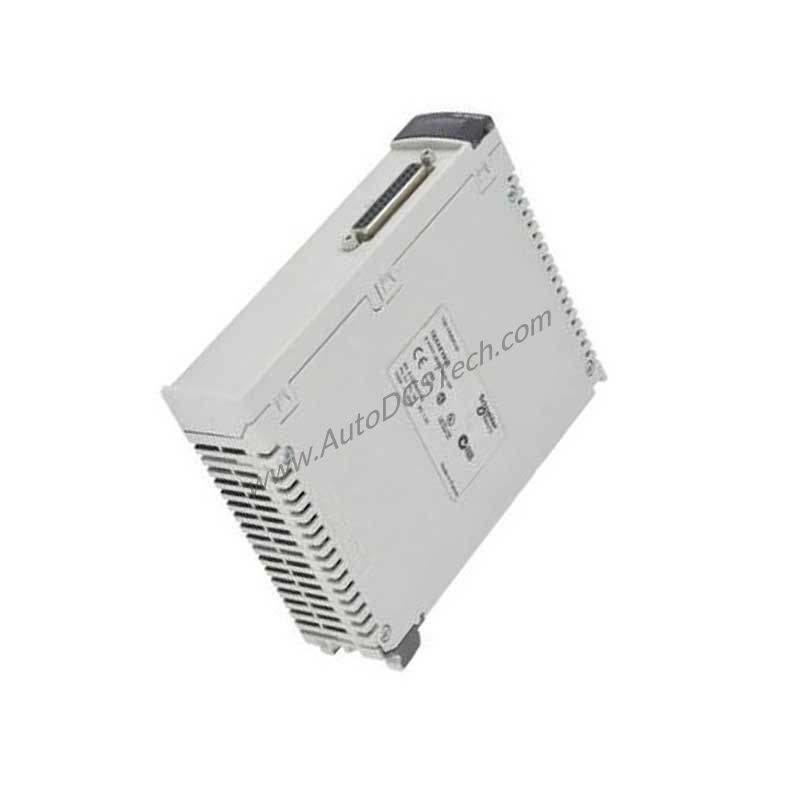
Before ordering the STBEPI2145K, verify your system requires a parallel interface for TeSys Quickfit or TeSys U applications. Ensure you have the STBXBA3000 mounting base and a compatible power distribution module (STBPDT3100 or STBPDT3105). The kit weighs only 0.165 kg and measures 170 mm deep, 28.1 mm high, and 128.3 mm wide, fitting easily into control panels. AutoDCSTech stocks this item and can confirm availability and lifecycle status. Please verify current lifecycle status and availability with AutoDCSTech before ordering.
Availability & Condition at AutoDCSTech
| Part Number | STBEPI2145K |
|---|---|
| Availability | In Stock |
| Condition | New |
| Warranty | One Year |
| Origin | France |