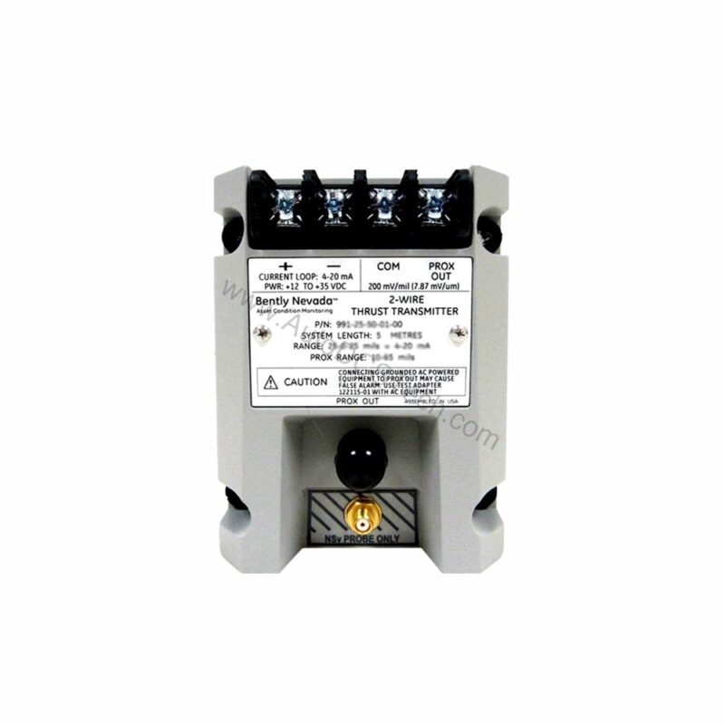
Introduction to the Bently Nevada 991-25-50-01-CN Thrust Transmitter
When axial shaft position drifts beyond safe limits, the 991-25-50-01-CN from Bently Nevada provides early warning. This probe vibration transmitter converts proximity probe signals into a standard 4-20 mA loop, enabling continuous thrust monitoring in rotating machinery. Designed for DIN rail mounting, it integrates easily into existing control panels.
As a thrust transmitter, it accepts input from a single non-contacting 3300 NSv proximity probe and extension cable. The unit operates on +12 to +35 Vdc input at the transmitter terminal, making it versatile for various power supplies. Its compact 0.43 kg (0.9 lbm) weight simplifies installation and replacement.
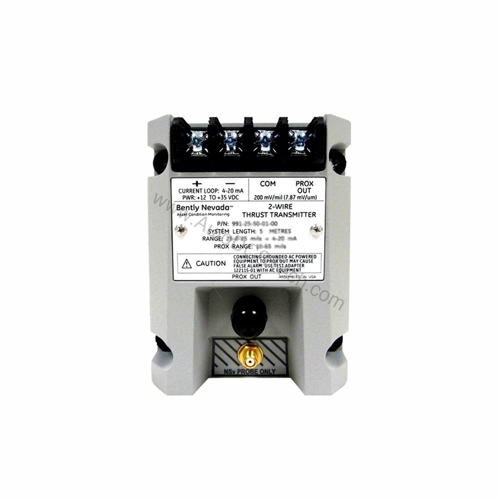
With a full-scale option of 25-0-25 mils, this model suits applications requiring precise axial position measurement. The 5.0 meters (16.4 feet) system length option provides flexibility in probe placement. Country-specific CN approvals ensure compliance with regional standards.
Key Features and Technical Specifications
The 991-25-50-01-CN offers several features that enhance reliability and ease of use. Its 4-20 mA output signal is industry-standard, simplifying integration with PLCs, DCS, and SCADA systems. The transmitter's linear range of 0.25 to 1.65 mm for Prox Out supports both 0.6-0-0.6 mm and 25-0-25 mils current loop linear ranges.
- Input: Accepts 1 non-contacting 3300 NSv proximity probe and extension cable.
- Power: Requires +12 to +35 Vdc input at the transmitter terminal.
- Output: 4 to 20 mAdc over specified full-scale range in 2-wire configuration.
- Accuracy: Within ±1.5% over specified full scale range (typical).
- Maximum Loop Resistance: 1,000 Ω including cable at 35 Vdc.
- Current Limiting: 23 mA typical.
- Zero and Span: Non-interacting external adjustments.
- Not OK/Signal Defeat: Output drops below 3.6 mA within 100 µs after a Not OK condition.
The Not OK/Signal Defeat feature is critical for safety. It forces the output below 3.6 mA within 100 µs, alerting operators to faults. Recovery occurs within 0.1 seconds after the condition clears, minimizing downtime.
Applications and Use Cases
This thrust transmitter is ideal for axial position monitoring in turbines, compressors, and pumps. In power generation, it helps prevent thrust bearing damage by providing early warning of shaft movement. Similarly, in oil and gas facilities, it monitors axial displacement in critical rotating equipment.
For maintenance engineers, the 4-20 mA output simplifies troubleshooting. It allows direct connection to existing analog input modules without additional signal conditioning. The DIN rail mounting option (35 mm clips) speeds up installation and reduces panel space.
Moreover, the transmitter's wide operating temperature range (-35°C to +85°C) ensures reliable performance in harsh environments. Storage temperature extends from -51°C to +100°C, accommodating seasonal shutdowns.
Installation and Setup
Mount the 991-25-50-01-CN on a standard 35 mm DIN rail using the included clips. Ensure adequate clearance for wiring and adjustments. Connect the proximity probe and extension cable to the transmitter input. Then, wire the 4-20 mA loop to your monitoring system, observing polarity.
Power the transmitter with +12 to +35 Vdc at the terminal. Verify loop resistance does not exceed 1,000 Ω at 35 Vdc to maintain accuracy. After power-up, perform zero and span adjustments using the non-interacting external controls. Calibrate according to the full-scale range (25-0-25 mils) for accurate readings.
For optimal performance, route signal cables away from high-voltage sources. Use shielded cable for the probe connection to minimize electromagnetic interference. Follow the manufacturer's manual for detailed wiring diagrams and torque specifications.
Maintenance and Reliability
Regular inspection of the transmitter and probe is essential for long-term reliability. Check for loose connections, corrosion, or physical damage. Verify the 4-20 mA output matches expected values during routine calibration checks. The transmitter's sealed enclosure protects against dust and moisture, but periodic cleaning of the exterior is recommended.
Because the unit operates over a wide temperature range, thermal stress is minimal. However, ensure ventilation around the DIN rail to prevent overheating. The current limiting feature (23 mA typical) protects the loop from overcurrent conditions, reducing the risk of damage to downstream devices.
When troubleshooting, use the Not OK signal as a diagnostic tool. If the output drops below 3.6 mA, check probe integrity, cable continuity, and power supply. The fast response (100 µs) helps identify transient faults quickly. Always refer to the Bently Nevada manual for specific maintenance procedures.
Compatibility and Integration
The 991-25-50-01-CN integrates seamlessly with most control systems that accept 4-20 mA analog inputs. It is compatible with Bently Nevada's 3300 NSv proximity probe system, ensuring accurate measurement. The 2-wire configuration simplifies wiring and reduces installation cost.
For existing installations, this transmitter can replace older thrust monitoring modules without major modifications. Its DIN rail mounting aligns with standard panel layouts. The output signal can be fed directly into PLC analog cards, DCS input modules, or standalone indicators.
No special communication protocols are required, making it a plug-and-play solution. The transmitter's linear range (0.25 to 1.65 mm) matches common axial displacement ranges, ensuring compatibility with most machinery. For specific integration questions, consult AutoDCSTech's technical team.
Common Issues and Troubleshooting
One common issue is loop wiring errors, such as reversed polarity, which can prevent output. Always verify connections against the manual. Another issue is excessive loop resistance, which can degrade accuracy. Keep loop resistance below 1,000 Ω at 35 Vdc.
If the output is stuck at 4 mA, check for probe damage or incorrect gap settings. The zero adjustment may need recalibration. If the output exceeds 20 mA, verify the full-scale setting and probe linearity. The Not OK condition may indicate a probe fault or cable break.
To avoid these problems, perform regular calibration and visual inspections. Use the non-interacting zero and span adjustments to fine-tune readings. If issues persist, contact AutoDCSTech for technical support or replacement parts.
Support and Availability
The 991-25-50-01-CN is available at AutoDCSTech. Contact our team for current stock status and lead times. We provide technical support to help with selection, installation, and troubleshooting. Ensure you verify lifecycle status before ordering, as availability may vary.