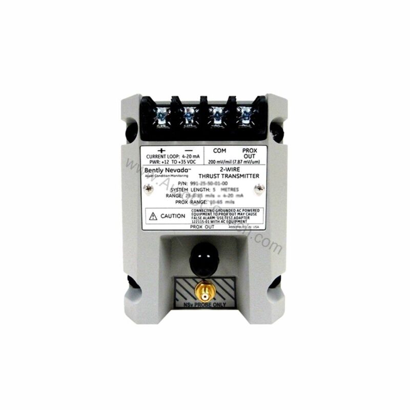
Introduction to the 991-25-50-02-01 Bently Nevada Thrust Transmitter
When axial shaft position drifts beyond safe limits, the 991-25-50-02-01 from Bently Nevada provides a critical early warning. This probe vibration transmitter converts non-contacting proximity probe signals into a standard 4-20 mA loop, enabling continuous monitoring of thrust bearing wear and rotor position. Designed for DIN rail mounting, it integrates easily into existing control panels and is suitable for axial thrust measurement in rotating machinery.
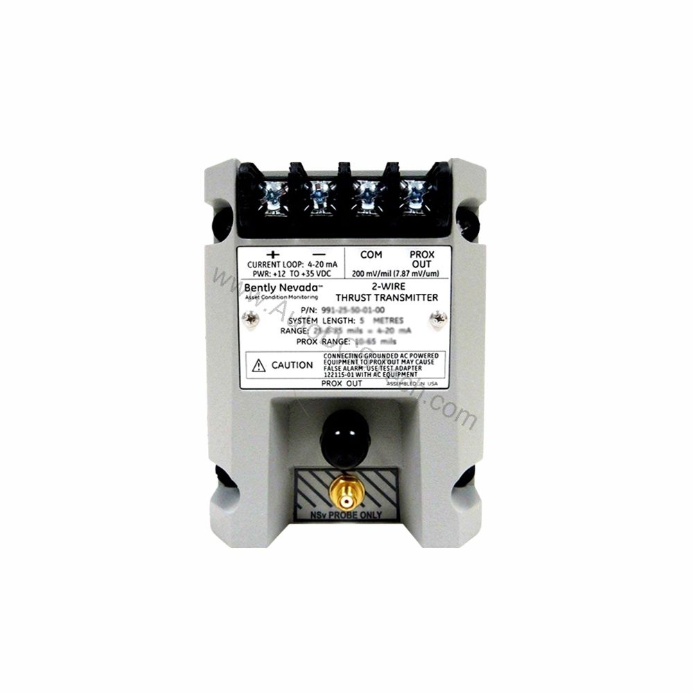
Key Features and Technical Specifications
The 991-25-50-02-01 delivers precise, loop-powered signal conditioning. Its key specifications include:
- Model 991 thrust transmitter with a full-scale range of 25-0-25 mils (0.6-0-0.6 mm).
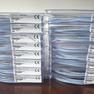
- Accepts one non-contacting 3300 NSv proximity probe and extension cable.
- Requires +12 to +35 Vdc input at the transmitter terminal.
- Outputs 4-20 mAdc over the specified full-scale range in a 2-wire configuration.
- Loop accuracy within ±1.5% over the full-scale range (typical).
- Maximum loop resistance of 1,000 ohms including cable at 35 Vdc.
- Current limiting at 23 mA typical.
- Zero and span adjustments are non-interacting and external.
- Not OK/Signal Defeat: output drops below 3.6 mA within 100 µs of a Not OK condition; restores within 0.1 seconds after removal.
- Operating temperature: -35°C to +85°C (-31°F to +185°F); storage: -51°C to +100°C (-60°F to +212°F).
- Weight: 0.43 kg (0.9 lbm).
- Agency approval: CSA Division 2.
This transmitter is engineered for axial thrust monitoring, where early detection of thrust bearing wear prevents catastrophic machine failure. Its fast Not OK response (less than 3.6 mA within 100 µs) ensures that control systems receive an immediate alarm, minimizing downtime and protecting capital equipment.
Applications and Use Cases
The 991-25-50-02-01 is ideal for turbomachinery, compressors, and large pumps where axial shaft position is critical. In such applications, the transmitter continuously monitors thrust bearing clearance. If the shaft moves beyond the setpoint, the output signal drops, triggering an alarm or shutdown. This proactive approach reduces the risk of bearing damage and unplanned outages. Furthermore, because the transmitter outputs a standard 4-20 mA signal, it can interface directly with PLCs, DCS, and SCADA systems, simplifying integration.
Installation and Setup
Mount the 991-25-50-02-01 on a DIN rail in a suitable enclosure. Connect the 3300 NSv proximity probe and extension cable to the transmitter input. Then wire the 4-20 mA loop to the monitoring system, ensuring the loop resistance does not exceed 1,000 ohms at 35 Vdc. Power the transmitter with +12 to +35 Vdc at the terminal. Use the external zero and span adjustments to calibrate the output to the desired full-scale range. Always follow the manufacturer's manual for detailed wiring and calibration procedures.
Maintenance and Reliability
Regular inspection of the 991-25-50-02-01 is essential for long-term reliability. Check the integrity of the probe cable and connections periodically. Verify that the DIN rail mounting is secure and that the ambient temperature stays within the specified operating range. Because the transmitter is CSA Division 2 approved, it is suitable for hazardous locations, but routine checks should still be performed per site safety procedures. The non-interacting zero and span adjustments simplify recalibration, reducing maintenance time and cost.
Troubleshooting Common Issues
If the output signal is not within the expected range, first verify the supply voltage is between +12 and +35 Vdc. Next, check the loop resistance; if it exceeds 1,000 ohms, the output may be limited. If the output drops below 3.6 mA, a Not OK condition may be present—inspect the probe and cable for damage. Also, confirm that the zero and span settings are correct for the 25-0-25 mils range. If problems persist, consult the Bently Nevada documentation or contact AutoDCSTech for support.
Product Support and Availability
The 991-25-50-02-01 is available from AutoDCSTech. For lifecycle status and ordering information, please contact our team. We are ready to assist with your machinery protection needs.