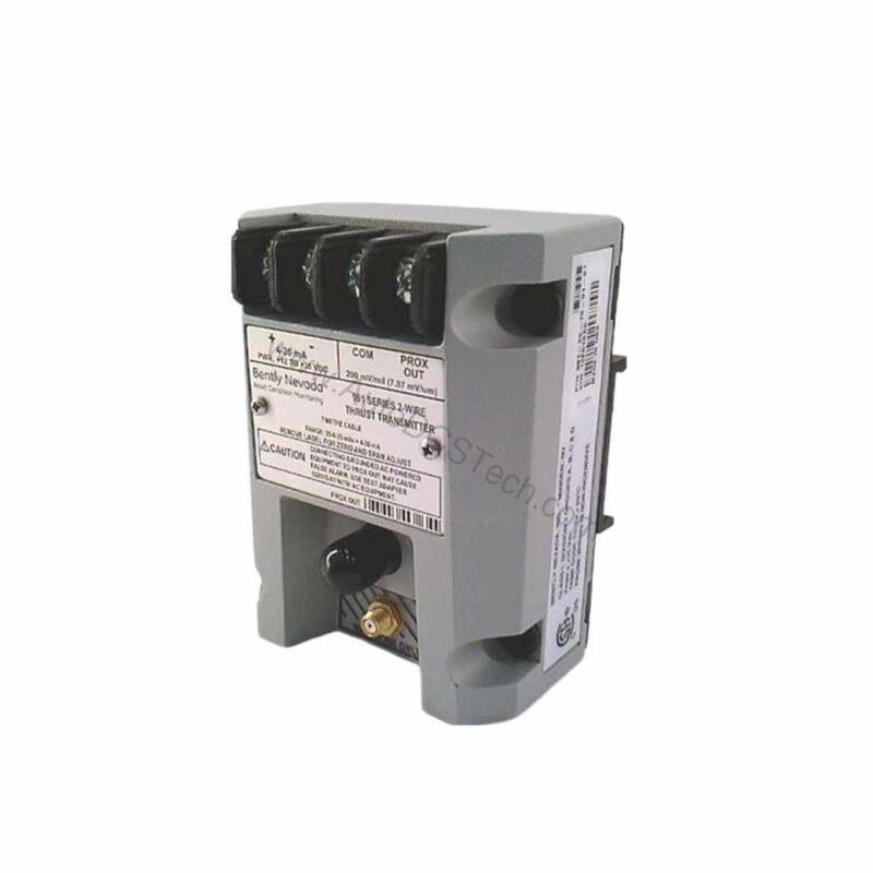
Introduction to the 991-25-70-02-CN
When axial thrust monitoring demands precision, the 991-25-70-02-CN from Bently Nevada delivers reliable performance. This probe vibration transmitter converts proximity probe signals into a standard 4-20 mA output. Designed for industrial turbomachinery, it helps protect critical assets from thrust-related damage.
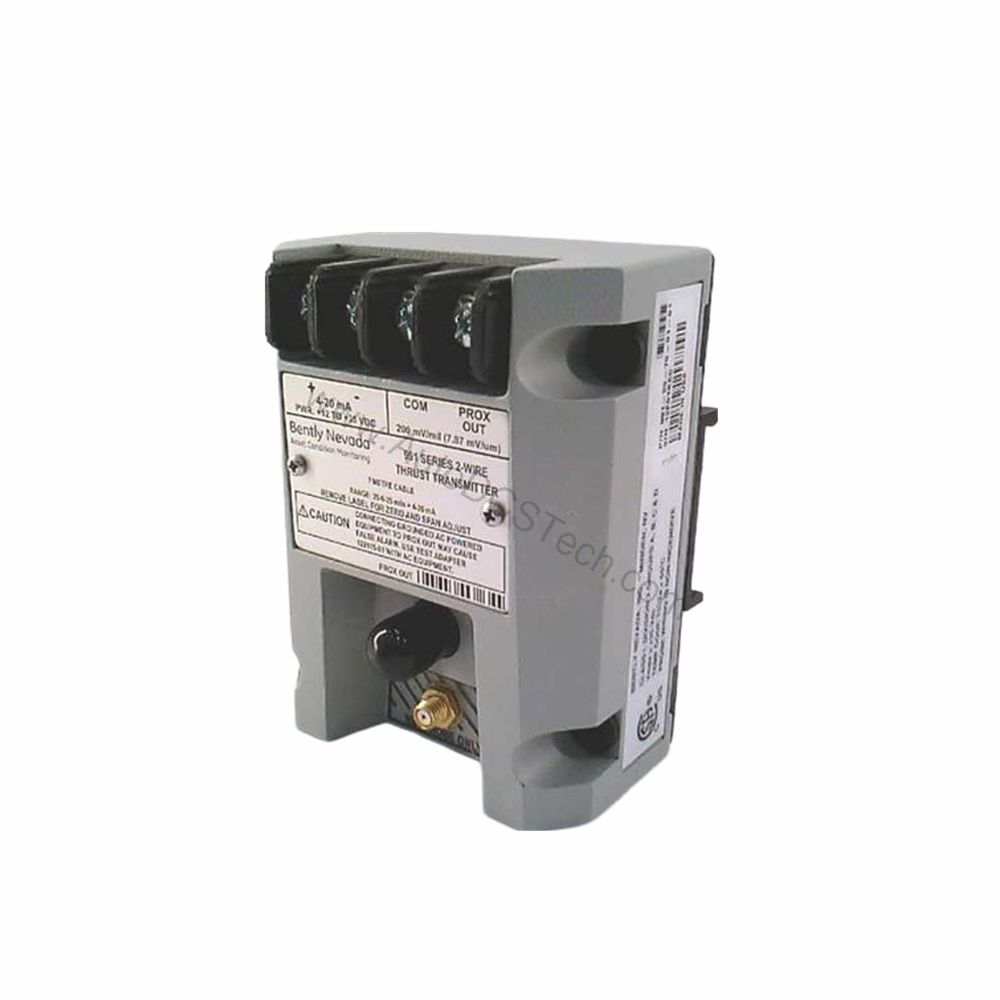
Key Features and Technical Specifications
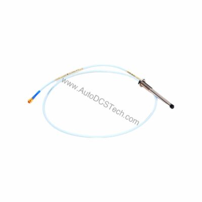
The 991-25-70-02-CN is a thrust transmitter with a full-scale range of 25-0-25 mils. It operates with a system length of 7.0 meters (23.0 feet) and mounts via bulkhead screws. The unit accepts one non-contacting 3300 NSv proximity probe and extension cable.
- Output signal: 4-20 mA in a 2-wire configuration
- Power requirement: +12 to +35 Vdc input at the transmitter terminal
- Linear range: 0.25 to 1.65 mm for Prox Out; suitable for 0.6-0-0.6 mm or 25-0-25 mils current loop linear ranges
- Accuracy: Within ±1.5% over specified full-scale range (typical)
- Maximum loop resistance: 1,000 Ω including cable at 35 Vdc
- Current limiting: 23 mA typical
- Operating temperature: -35°C to +85°C (-31°F to +185°F)
- Storage temperature: -51°C to +100°C (-60°F to +212°F)
- Weight: 0.43 kg (0.9 lbm)
- Mounting: DIN rail
- Agency approval: -CN (country-specific approvals)
One distinctive feature is the fast Not OK response. The signal output drops to less than 3.6 mA within 100 µs after a Not OK condition occurs. This rapid response helps alert operators to potential issues quickly.
Applications and Use Cases
The 991-25-70-02-CN is used for axial position monitoring in rotating machinery. It is suitable for turbines, compressors, and pumps where thrust bearing wear can lead to catastrophic failure. By providing a continuous 4-20 mA signal, it integrates easily with PLCs and DCS systems. This transmitter helps maintenance teams detect abnormal thrust movement early, reducing unplanned downtime.
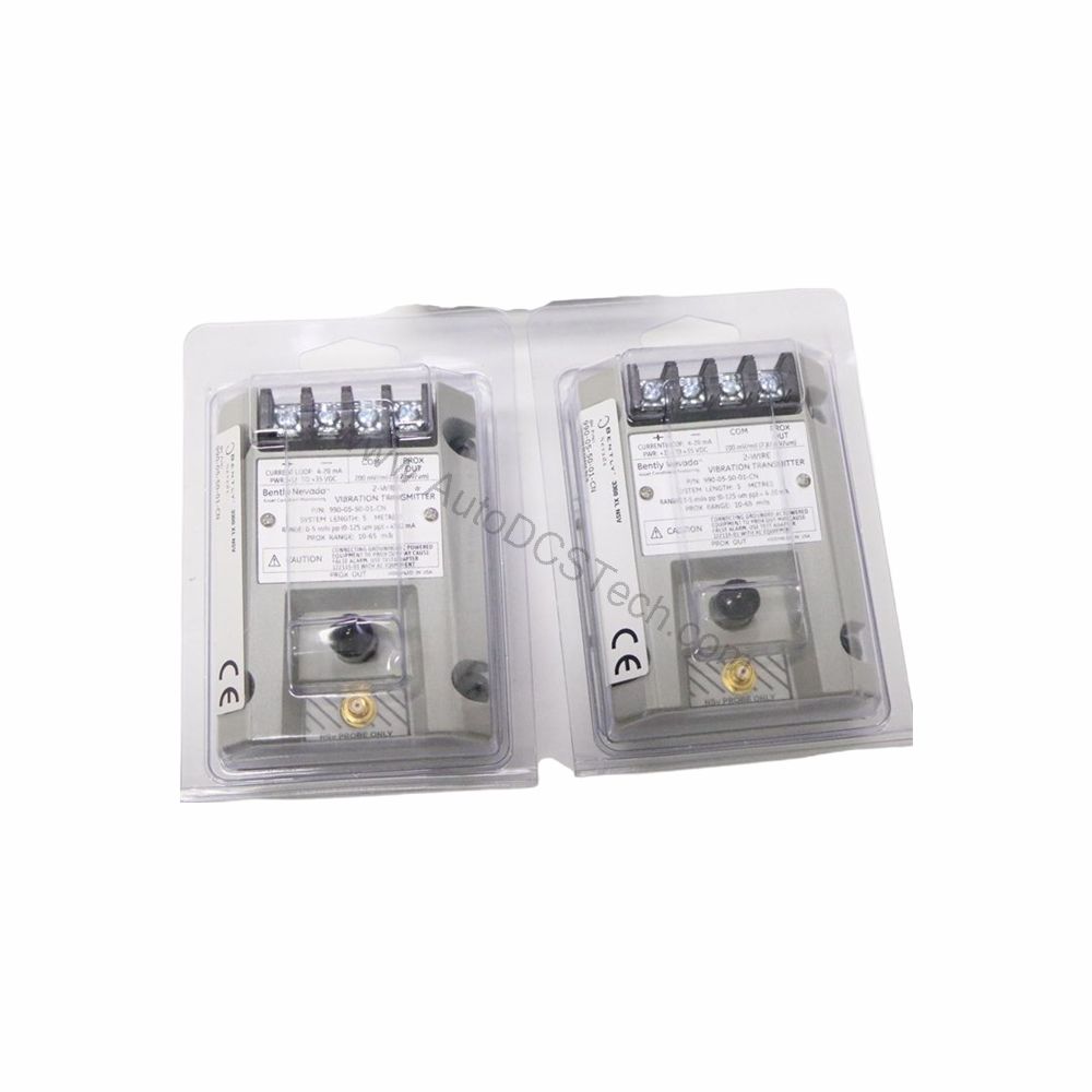
Installation and Setup
Mount the 991-25-70-02-CN on a standard DIN rail. Connect the 3300 NSv proximity probe and extension cable to the transmitter input. Wire the output to a 4-20 mA loop with a maximum resistance of 1,000 Ω at 35 Vdc. Ensure the power supply provides +12 to +35 Vdc at the transmitter terminal. Use the non-interacting external zero and span adjustments for calibration. Verify the system length of 7.0 meters matches your installation requirements.
Maintenance and Reliability
Regular inspection of the 991-25-70-02-CN ensures long-term reliability. Check the mounting and connections periodically. Verify the output signal remains within the specified accuracy of ±1.5%. Monitor the loop resistance to stay below 1,000 Ω. Keep the transmitter within the operating temperature range to avoid performance degradation. Following these practices helps extend service life and maintain measurement integrity.
Troubleshooting and Common Issues
If the output signal is missing or erratic, check the power supply voltage at the transmitter terminal. Ensure the loop resistance does not exceed 1,000 Ω. Verify the probe and extension cable are properly connected. If a Not OK condition occurs, the output drops below 3.6 mA within 100 µs. After the condition is removed, the signal restores within 0.1 seconds. For persistent issues, consult the Bently Nevada manual or contact AutoDCSTech.
Product Support and Availability
The 991-25-70-02-CN is available from AutoDCSTech. Please verify current lifecycle status and availability with AutoDCSTech before ordering. For technical support, contact our team.