Introduction to the 991-25-70-02-00
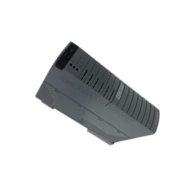
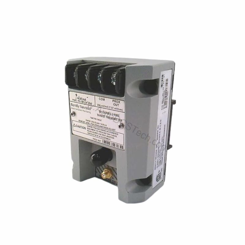
When a rotating machine experiences unexpected axial thrust, the consequences can be severe. The 991-25-70-02-00 from Bently Nevada is engineered to address this challenge. This probe vibration transmitter converts proximity probe signals into a standard 4-20 mA output, enabling continuous monitoring of thrust position. Designed for axial use, it helps protect critical equipment from damage caused by excessive shaft movement.
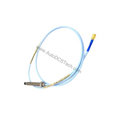
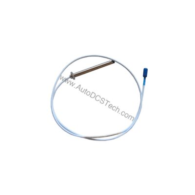
Part of the 991 series, this transmitter is built for reliability in industrial environments. It accepts input from a single non-contacting 3300 NSv proximity probe and extension cable, making it a versatile solution for many rotating machinery applications.
Key Features and Technical Specifications
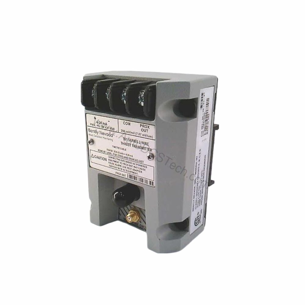
The 991-25-70-02-00 offers a range of features that simplify integration and enhance performance. Below are the core specifications:
- Full-scale option: 25-0-25 mils (0.6-0-0.6 mm) linear range for current loop.
- Output signal: 4-20 mA DC in a 2-wire configuration.
- Power requirement: +12 to +35 Vdc input at the transmitter terminal.
- Loop accuracy: Within ±1.5% over specified full-scale range (typical).
- Maximum loop resistance: 1,000 ohms including cable at 35 Vdc.
- Current limiting: 23 mA typical.
- Not OK/Signal Defeat: Output drops below 3.6 mA within 100 µs after a fault, restoring within 0.1 seconds.
- Mounting: DIN rail with bulkhead screw option.
- System length: 7.0 meters (23.0 feet) cable.
One distinctive feature is the non-interacting external zero and span adjustments. This allows field calibration without affecting the other parameter, simplifying setup and maintenance.
Applications and Use Cases
The 991-25-70-02-00 is primarily used for axial thrust monitoring in turbomachinery, compressors, and large pumps. By providing a 4-20 mA signal, it integrates easily with PLCs, DCS, and SCADA systems. This transmitter is suitable for both new installations and retrofits, offering a cost-effective way to enhance machine protection.
In a typical scenario, the transmitter is mounted on a DIN rail in a control cabinet, while the proximity probe is installed near the thrust bearing. The 4-20 mA output can be fed into a vibration monitor or safety system, providing real-time data to operators.
Installation and Setup
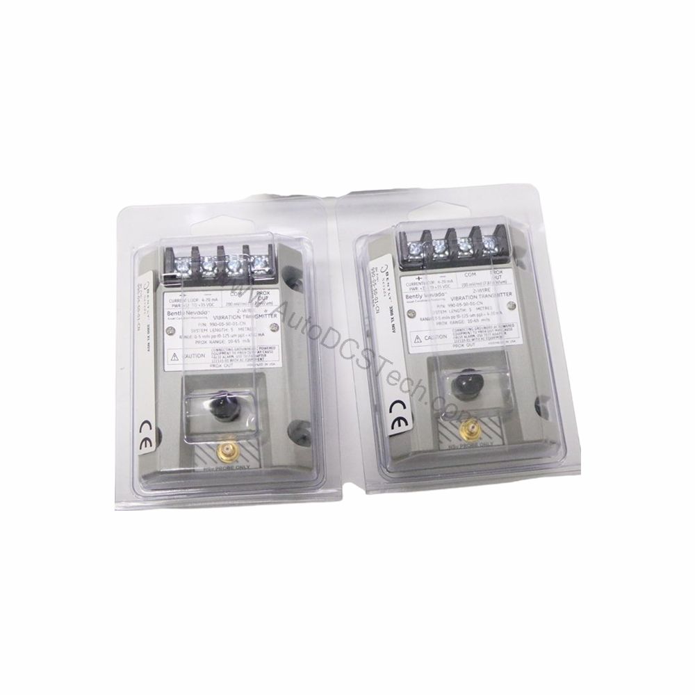
Proper installation is critical for accurate readings. The 991-25-70-02-00 mounts easily on a standard DIN rail. The bulkhead screw mounting option provides a secure alternative for panel mounting. Ensure the system length (7.0 meters) is appropriate for your application, as this includes the probe and extension cable.
Wiring is straightforward: connect the power supply (+12 to +35 Vdc) and the 4-20 mA loop to the appropriate terminals. The 2-wire configuration minimizes cabling. After installation, perform a zero and span calibration using the external adjustments. Always follow the manufacturer's manual for detailed procedures.
Maintenance and Reliability
Routine maintenance is minimal but essential. Periodically verify the output signal against a known reference to ensure accuracy. Check all connections for tightness and inspect the cable for wear or damage. The transmitter operates within a temperature range of -35°C to +85°C, making it suitable for harsh environments. Storage temperature ranges from -51°C to +100°C.
Because the transmitter is solid-state, there are no moving parts to wear out. However, environmental factors such as vibration, moisture, and extreme temperatures can affect performance. Regular inspection helps identify potential issues before they lead to downtime.
Compatibility and Integration
The 991-25-70-02-00 is designed to work with Bently Nevada 3300 NSv proximity probes. The 4-20 mA output is universally compatible with most control systems, eliminating the need for specialized interfaces. This makes it an excellent choice for upgrading existing monitoring systems or integrating into new ones.
For applications requiring higher accuracy, the ±1.5% typical loop accuracy ensures reliable data. The Not OK/Signal Defeat feature provides fast fault indication, enhancing overall system safety.
Common Issues and Troubleshooting
If the output is not as expected, check the power supply voltage at the transmitter terminal. Ensure it is within +12 to +35 Vdc. Verify the loop resistance does not exceed 1,000 ohms, as higher resistance can affect the signal. If the output goes below 3.6 mA, the transmitter may be in a Not OK state. Check the probe and cable for damage or disconnection.
Another common issue is incorrect zero or span calibration. Use the external adjustments to reset these values. If problems persist, consult the Bently Nevada documentation or contact AutoDCSTech for support.
Support and Availability
AutoDCSTech offers the 991-25-70-02-00 for immediate shipment. As an industrial automation parts supplier, we ensure genuine Bently Nevada products. Contact our team for lifecycle status and availability confirmation before ordering.