Technical Specifications Breakdown
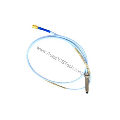
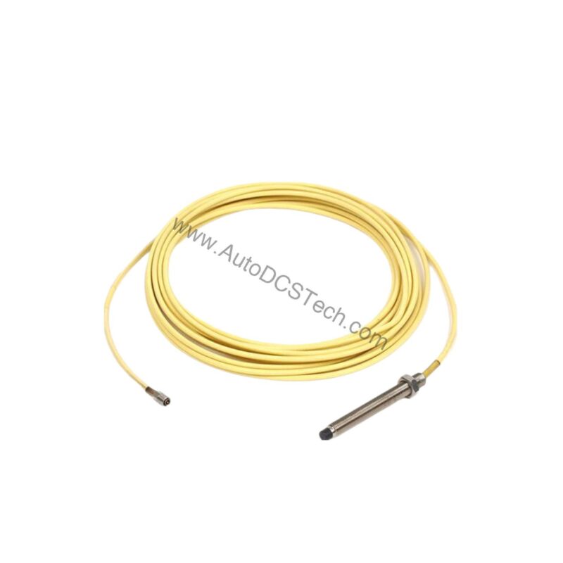
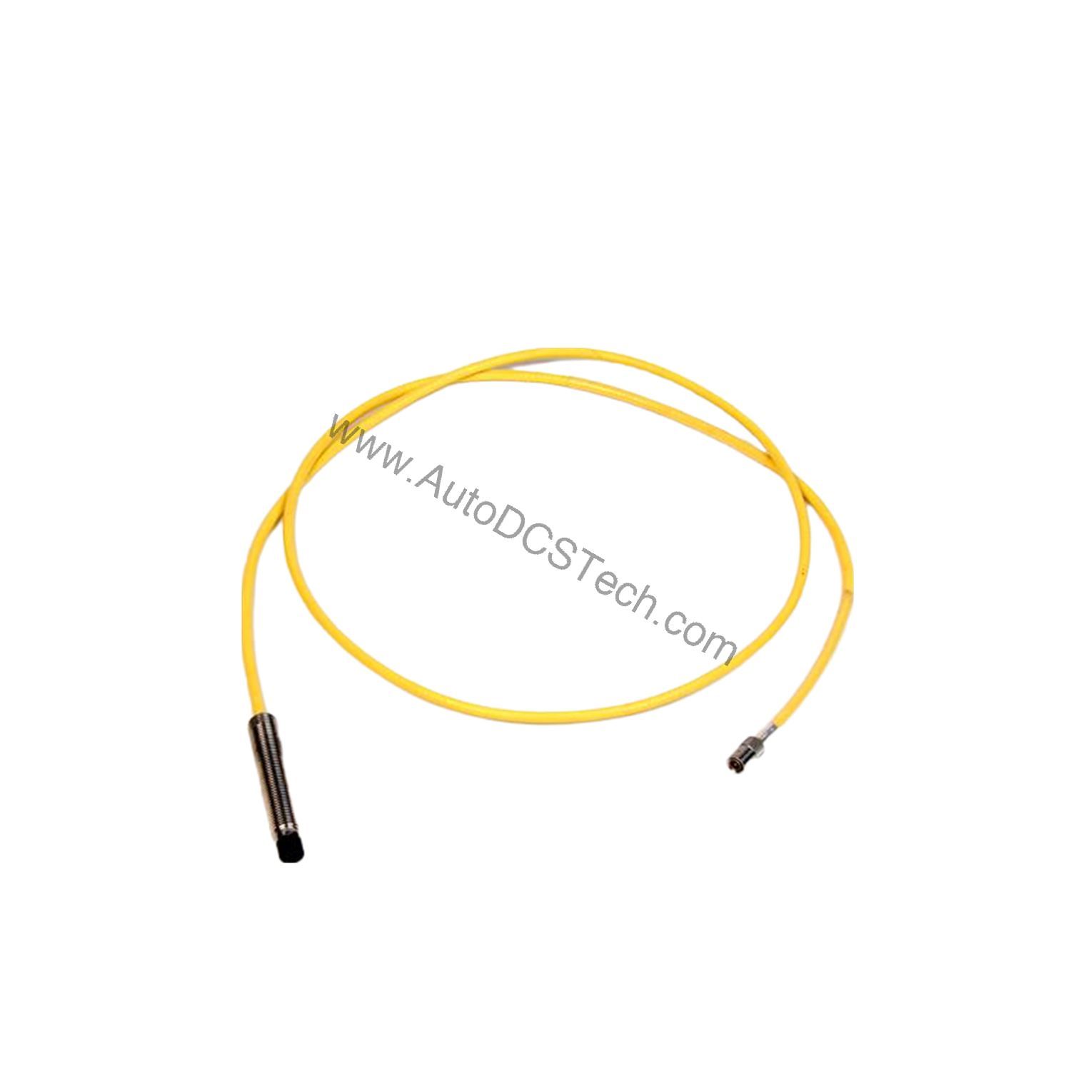
Key parameters for the 21504-00-20-10-02 are listed below for quick reference:
| Feature | Specification |
|---|---|
| Model | 21504 7200 Proximity Transducer System |
| Probe Diameter | 8 mm |
| Configuration Threads | 3/8-24 |
| Unthreaded Length Option | 00 (0 mm) |
| Overall Case Length Option | 20 (200 mm) |
| Total Length Option | 10 (1.0 metre / 39 inches) |
| Connector Option | 02 (miniature male coaxial connector) |
| Input Power | -17.5 Vdc to -26 Vdc at 12 mA maximum consumption |
| Calibrated Range | 80 mils (2.0 mm) |
| Scale Factor | 200 mV/mil (7.87 V/mm), ±4% (system calibrated) |
| Frequency Response | 0 to 10 kHz (0 to 600,000 cpm) |
| Operating Temperature (Proximitor) | -60°F to +212°F (-51°C to +100°C) |
| Operating Temperature (Probe/Extension Cable) | -30°F to +350°F (-34°C to +177°C) |
| Relative Humidity | To 95%, noncondensing |
| System Weight | 1.3 lbs (0.59 kg) |
Industry Applications and Operational ROI
Typical applications include:
- Steam and Gas Turbines: Monitor radial vibration and thrust position to avoid blade rubs and bearing damage.
- Centrifugal Compressors: Detect shaft orbit changes that indicate surge or imbalance.
- Large Pumps and Motors: Provide early warning of misalignment or bearing wear.
By integrating the 21504-00-20-10-02 into a condition monitoring program, operators reduce unplanned downtime and extend machinery life. The 200 mV/mil scale factor offers high sensitivity for detecting subtle changes, while the 0 to 10 kHz frequency response captures both low-speed and high-speed events.
Installation and Setup Guidance
Proper installation is essential for accurate readings. Follow these engineering best practices:
- Mount the probe with the specified 3/8-24 threaded configuration into a rigid, non-ferrous bracket.
- Ensure the unthreaded length (0 mm) and overall case length (200 mm) match the target gap requirements.
- Connect the miniature male coaxial connector securely to the extension cable, avoiding sharp bends.
- Power the Proximitor with -17.5 Vdc to -26 Vdc at 12 mA maximum. Verify polarity and voltage before energizing.
- Calibrate the system as an unit to achieve the ±4% scale factor accuracy. Adjust gap voltage to the midpoint of the calibrated range (approximately 10 mils from probe face).
Maintenance and Reliability
The probe and extension cable withstand harsh conditions: -30°F to +350°F and up to 95% relative humidity. For 8 mm probes, the tip resists direct contact with air, water, lube oil, ammonium hydroxide, 10% sulfuric acid, MEK, and DMF. Inspect the probe face and cable periodically for contamination or mechanical damage. Keep the connector clean and dry. No internal adjustments are required.
Precision Vibration Monitoring for Critical Machinery
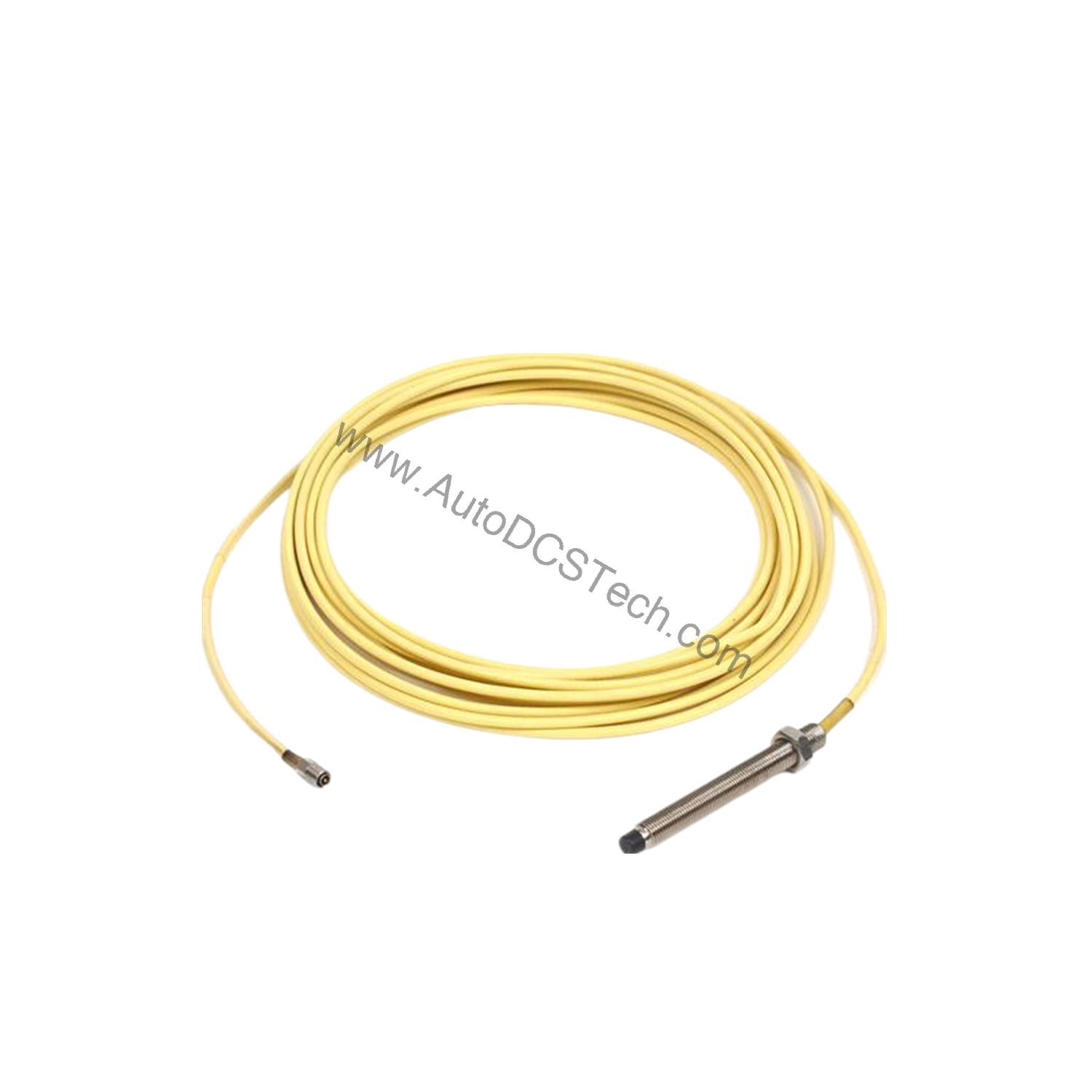
Industrial rotating machinery demands reliable, real-time vibration monitoring to prevent catastrophic failures. The Bently Nevada 21504-00-20-10-02 is a precision 8 mm proximity probe system designed for continuous shaft vibration and position measurement in turbines, compressors, pumps, and other critical assets. This component delivers accurate displacement data essential for predictive maintenance and machine protection.
Compatibility and Integration
This transducer system is part of the Bently Nevada 7200 series and interfaces directly with compatible Proximitor monitors. The 1.0 metre cable with coaxial connector simplifies wiring in standard junction boxes. For extended distances, use approved extension cables. The system outputs a proportional DC voltage (200 mV/mil) that connects to vibration monitoring systems, PLCs, or distributed control systems.
Selection Guide and Purchasing Advice
When selecting a replacement or new proximity probe, verify the total length, thread size, and connector type. AutoDCSTech stocks this model as new and original in factory packing, backed by a 12-month warranty. Please verify current lifecycle status and availability with AutoDCSTech before ordering.
Troubleshooting and Common Issues
- No output signal: Check power supply voltage (-17.5 to -26 Vdc) and current draw (12 mA max). Inspect coaxial connector for damage.
- Erratic readings: Verify probe gap is within calibrated range (10 to 80 mils). Look for loose mounting or cable strain.
- Scale factor drift: Recalibrate the system as a matched set. Confirm target material matches calibration standard.
- Temperature sensitivity: Note that scale factor may shift typically -3% at +150°F and 50 mils gap. Account for this in high-temperature applications.
Availability & Condition at AutoDCSTech
| Part Number | 21504-00-20-10-02 |
|---|---|
| Availability | In Stock |
| Condition | New |
| Warranty | One Year |
| Origin | US |