Introduction
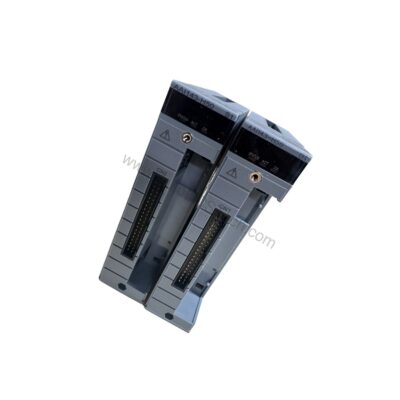
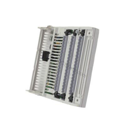
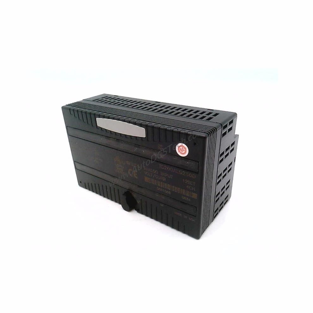
In modern industrial automation, the ability to accurately capture analog signals from sensors and transmitters is foundational to process control. The GE IC200ALG260 VersaMax analog input module addresses this need with precision and flexibility. As part of the trusted VersaMax I/O platform, this module converts analog signals from field devices into digital data for your PLC or control system.
Technical Specifications Breakdown
The IC200ALG260 features eight single-ended analog inputs arranged in a single group. Key specifications include:
- Analog Input Resolution: 12 bits
- Voltage Type: Unipolar or Bipolar
- Operating Modes: Voltage or Current
- Response Time: 5.0 ms
- Update Rate: 0.4 ms
- Filter Response Time: 5 milliseconds
- Backplane Current Consumption: 125 mA at 5 VDC
- Optical Isolation: 250 VAC continuous; 1500 VAC for 1 minute
- LED Indicators: OK and INT PWR
- Configuration Parameters: Range select, Mode select
- Diagnostics: Loss of internal power
- Reaction to Module Error: Hold last state; Go to pre-defined value
These specifications make the IC200ALG260 suitable for applications requiring reliable signal conversion with moderate speed and isolation.
Industry Applications
The IC200ALG260 is used for monitoring analog signals in manufacturing, water treatment, and energy management systems. For example, in a water treatment plant, it can read 4-20 mA signals from pressure transmitters and flow meters. In a packaging line, it can accept ±10 VDC signals from position sensors. Its single-ended input design simplifies wiring in grounded reference systems.
Installation & Setup Guidance
When installing the IC200ALG260, ensure the backplane provides 5 VDC power. The module does not require an external power supply unless transceiver devices are connected. Configure the operating mode (voltage or current) using the Range select and Mode select parameters. For current mode, use 4-20 mA signals; for voltage mode, use 0 to 10 VDC (unipolar) or -10 to +10 VDC (bipolar). The module defaults to voltage mode. Single-ended wiring requires the analog measurement reference to be connected to ground. To minimize electromagnetic interference (EMI), use shielded cables and proper signal conditioning.
Maintenance & Reliability
Routine inspection of the IC200ALG260 should include checking the OK and INT PWR LEDs. A green OK LED indicates backplane power; a green INT PWR LED confirms field power for analog circuits. The module's optical isolation (250 VAC continuous, 1500 VAC for 1 minute) protects against voltage transients. No thermal derating is required. For reliable long-term operation, ensure the backplane current consumption stays within 125 mA at 5 VDC.
Compatibility & Integration
The IC200ALG260 integrates with the VersaMax I/O platform and is compatible with GE Fanuc and Emerson Automation controllers. It does not require external power for the analog circuits, as field power is generated internally. The module supports single-ended wiring and can be configured for voltage or current modes. No communication protocols are specified in the data; integration is via the VersaMax backplane.
Selection Guide & Purchasing Advice
Before purchasing the IC200ALG260, verify your system's backplane voltage (5 VDC) and current capacity (125 mA per module). Confirm the required input type (voltage or current) and signal range. The module is a direct replacement for other VersaMax analog input modules with similar specifications. AutoDCSTech offers genuine GE IC200ALG260 modules with fast shipping and expert support. Please verify current lifecycle status and availability with AutoDCSTech before ordering.
Troubleshooting & Common Issues
- No OK LED: Check backplane power and connection. The module requires 5 VDC from the backplane.
- No INT PWR LED: Verify field power is present. The module generates internal field power, but external transceivers may need separate power.
- Inaccurate readings: Ensure correct mode selection (voltage or current) and proper signal conditioning. Single-ended inputs are susceptible to noise; use shielded cables.
- Module error: The IC200ALG260 can be configured to hold last state or go to a pre-defined value upon error. Check configuration parameters.
Frequently Asked Questions (FAQs)
Q1: What is the resolution of the IC200ALG260? A1: The IC200ALG260 has a 12-bit analog input resolution. Q2: Can the IC200ALG260 accept both voltage and current signals? A2: Yes, it can be configured for voltage mode (0 to 10 VDC unipolar or -10 to +10 VDC bipolar) or current mode (4-20 mA). Q3: Does the IC200ALG260 require an external power supply? A3: No, it draws power from the backplane (125 mA at 5 VDC). External power is only needed if transceiver devices are connected. Q4: How many inputs does the IC200ALG260 have? A4: It has eight single-ended analog inputs. Q5: What are the LED indicators on the IC200ALG260? A5: The module has two LEDs: OK (green, indicates backplane power) and INT PWR (green, indicates field power for analog circuits).
Availability & Condition at AutoDCSTech
| Part Number | IC200ALG260 |
|---|---|
| Availability | instock |
| Condition | New |
| Warranty | One Year |
| Origin | US |